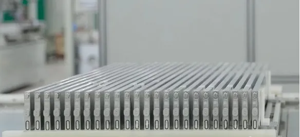
Lithium Battery Injection Process
Nov 24, 2023


Follow me on:
The role of lithium battery electrolyte is to facilitate the conduction of ions between the positive and negative electrodes, serving as the medium for charging and discharging, much like the blood in the human body. Ensuring that the electrolyte fully and uniformly permeates the interior of the lithium battery is a critical challenge. Therefore, the injection process is a crucial step that directly affects the performance of the battery.
The injection process involves quantitatively injecting electrolyte into the battery cell after assembly. The process can be divided into two steps: the first step is injecting the electrolyte into the interior of the cell, and the second step is ensuring that the injected electrolyte fully permeates the electrode sheets and the separator within the cell. The duration of the soaking process can impact the production cost of lithium-ion batteries. During this process, excessive injection of electrolyte can cause cell swelling, resulting in uneven thickness of the battery. Insufficient electrolyte injection can lead to reduced battery capacity and cycle life. Non-uniform electrolyte injection can result in inconsistent battery capacity and cycling performance.
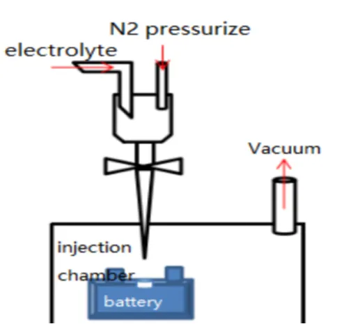
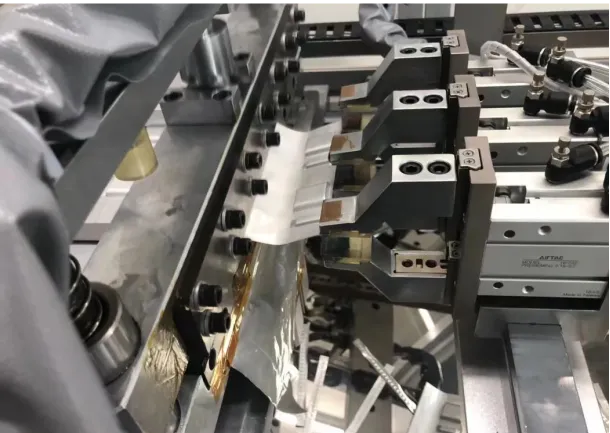
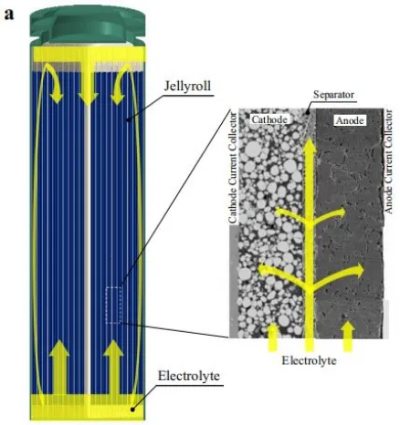
As shown in Figure 1, during the assembly process of commercial batteries, the electrolyte is injected into the sealed chamber through a metering pump. The battery is placed in the injection chamber, and then a vacuum pump creates a vacuum environment inside the battery. The injection nozzle is inserted into the battery’s injection port, the electrolyte injection valve is opened, and nitrogen gas is simultaneously used to pressurize the electrolyte chamber to 0.2-1.0 MPa. The pressure is maintained for a certain period, and then the injection chamber is vented to atmospheric pressure. Finally, the battery is left to stand for a long time (12-36 hours), allowing the electrolyte to fully infiltrate the positive and negative materials and the separator. After the injection is completed, the battery is sealed. The electrolyte is theoretically expected to permeate from the top of the battery into the separator and electrodes. However, in reality, a large amount of electrolyte flows downward and accumulates at the bottom of the battery, and then penetrates into the pores of the separator and electrodes through capillary pressure, as shown in Figure 2.
Typically, separators are made of porous hydrophilic materials with relatively high porosity, while electrodes are composed of porous media consisting of various particles. It is generally believed that the electrolyte permeates the separator at a faster rate compared to the electrodes. Therefore, the flow process of the electrolyte should first penetrate the separator and then permeate into the electrodes, as shown in Figure 2.
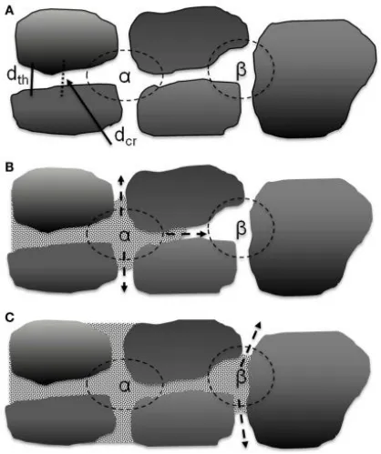
Between the large particles of the active materials in the electrode, larger pores are formed, and these pores are interconnected through narrow channels between two parallel particles. The electrolyte first gathers within these pores and then diffuses into the nearby throats. Therefore, the wetting rate of the electrolyte is primarily controlled by the throats and pore volumes that connect the interconnected pores. As shown in Figure 3, the α pores are composed of four particles and are interconnected with surrounding pores through four throats, while the β pores are composed of three particles and are interconnected with surrounding pores through three throats.
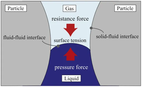
As shown in Figure 4, the diffusion mechanism of the electrolyte within the electrode pores can be considered as the interaction between three forces: the pressure from the electrolyte flow (Fl), the capillary force generated by surface tension (Fs), and the resistance from the air trapped within the pores (Fg). During the injection process, creating a vacuum within the battery reduces the resistance caused by the trapped air, while pressurizing the electrolyte enhances the driving force for liquid flow. Therefore, the combination of vacuum and pressure injection is beneficial for the infiltration of the electrolyte.
The capillary motion of the electrolyte can be described by the Washburn equation.
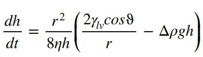
The variable “h” represents the liquid penetration height at time “t,” “r” denotes the radius of the capillary, “γlv” represents the liquid-gas surface tension, “ϑ” represents the contact angle, “Δρ” represents the density difference, and “η” represents the viscosity. It can be seen from this that the viscosity of the electrolyte, as well as the wetting contact angle and surface tension characteristics of the electrode, all have an impact on the infiltration process.
Electrolyte infiltration refers to the process of displacing air within the electrode pores. Due to the random distribution of pore sizes and shapes within the porous structure, different rates of electrolyte infiltration can occur, leading to the accumulation of air near the current collector, surrounded by electrolyte from the surroundings, and trapped within the electrode. The saturation level of electrolyte infiltration is always less than 1. While almost all large voids are filled with electrolyte, there are still numerous small voids present. These small voids represent residual air trapped by solid particles. Therefore, the key to improving the infiltration level is to minimize such residual air as much as possible.
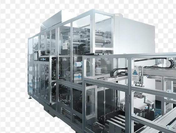
In summary, the injection process directly impacts the performance of lithium-ion batteries. By using injection equipment to accurately inject a predetermined amount of electrolyte into the battery cell, the technical challenge of uneven injection can be effectively addressed. Therefore, the injection equipment can be considered a key factor in achieving a proper injection effect during the injection process.