


Coating of electrode sheet generally refers to the process of uniformly applying a well-mixed slurry onto a current collector and drying the organic solvents present in the slurry. The coating quality has a significant impact on battery capacity, internal resistance, cycle life, and safety. Ensuring uniform coating of electrode sheet is crucial. The selection and control parameters of the coating method play an important role in the performance of lithium-ion batteries. This is mainly reflected in the following aspects:
1) Coating drying temperature control: If the drying temperature is too low during coating(related machine), the electrode sheet cannot be guaranteed to be completely dry. If the temperature is too high, the organic solvent inside the electrode sheet may evaporate too quickly, causing turtles to appear on the surface coating of the electrode sheet,cracking, falling off, etc.;
2) Coating surface density: If the coating surface density is too small, the battery capacity may not reach the nominal capacity. If the coating surface density is too high, it will easily cause a waste of ingredients. In severe cases, if there is excessive positive electrode capacity, due to lithium The precipitation forms lithium dendrites that pierce the battery separator and cause a short circuit, causing safety hazards;
3) Coating size: If the coating size is too small or too large, the positive electrode inside the battery may not be completely covered by the negative electrode. During the charging process, lithium ions are embedded from the positive electrode and move to the electrolyte that is not completely covered by the negative electrode. Medium, the actual capacity of the positive electrode sheet cannot be used efficiently. In severe cases, lithium dendrites will form inside the battery, which can easily pierce the separator and cause the internal circuit of the battery;
4) Coating thickness: Coating thickness that is too thin or too thick will have an impact on the subsequent electrode sheet rolling process and cannot guarantee the performance consistency of the battery electrode sheet.
In addition, electrode sheets coating is of great significance to the safety of the battery. Before coating, 5S work must be done to ensure that no particles, debris, dust, etc. are mixed into the electrode sheets during the coating process. If debris is mixed in, it will cause a micro short circuit inside the battery, and in severe cases, the battery may catch fire and explode.
1. Coating equipment and coating process selection
The generalized coating process includes: unwinding → splicing → pulling → tension control → coating → drying → alignment correcting → tension control → deviation correction → winding and other processes. The coating process is complex, and there are many factors that affect the coating effect, such as: the manufacturing accuracy of the coating equipment, the smoothness of the equipment operation, the control of dynamic tension during the coating process, the amount of air volume during the drying process, and temperature control curves will affect the coating effect, so it is extremely important to choose the appropriate coating process.
Generally, the following aspects need to be considered when selecting a coating method, including: the number of coating layers, the thickness of the wet coating, the rheological characteristics of the coating liquid, the required coating accuracy, the coating support or substrate, and cloth speed, etc.
In addition to the above factors, the specific conditions and characteristics of electrode sheet coating must also be combined. The coating characteristics of lithium-ion battery electrode sheets are: ① Double-sided single-layer coating; ② The slurry wet coating is thick (100~300μm); ③ The slurry is a non-Newtonian high-viscosity fluid; ④ The electrode sheets coating accuracy requirements High, similar to film coating accuracy; ⑤ The coating support is aluminum foil and copper foil with a thickness of 10 to 20 μm; ⑥ Compared with the film coating speed, the electrode sheets coating speed is not high. Considering the above factors, general laboratory equipment often uses the scraper type, consumer lithium-ion batteries mostly use the roller coating transfer type, and power batteries mostly use the slit extrusion method.
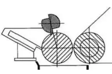
Scraper coating: The working principle is shown in Figure 1. The foil substrate passes through the coating roller and is in direct contact with the slurry trough. Excessive slurry is applied to the foil substrate. When the substrate passes between the coating roller and the scraper , the gap between the scraper and the substrate determines the thickness of the coating, and at the same time, the excess slurry is scraped off and reflowed, thereby forming a uniform coating on the surface of the substrate. Scraper type Main comma scraper. The comma scraper is one of the key components in the coating head. It is generally processed into a comma-like cutting edge on the surface of the round roller along the bus line. This scraper has high strength and hardness, and is easy to control the coating amount and coating accuracy. It is suitable for High solid content and high viscosity slurry.
Roller coating transfer type: The rotation of the coating roller drives the slurry, the amount of slurry transfer is adjusted through the comma scraper gap, and the rotation of the back roller and coating roller is used to transfer the slurry to the substrate. The process is shown in Figure 2. Roller transfer coating consists of two basic processes: (1) The rotation of the coating roller drives the slurry through the metering roller gap to form a slurry layer of a certain thickness; (2) The slurry layer of a certain thickness passes through the opposite direction of the coating roller and the The rotation of the backing roller transfers the slurry onto the foil to form a coating.
Schematic diagram of roller coating blade transfer coating process
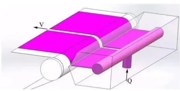
Slot die coating: As a precise wet coating technique, slot die coating operates as shown in Figure 3. The working principle involves the extrusion of coating liquid through the gap of a slot die at a specific pressure and flow rate, transferring it onto the substrate. Compared to other coating methods, slot die coating offers several advantages, such as high coating speed, high precision, and uniform wet thickness. The coating system is enclosed, preventing contaminants from entering during the coating process, resulting in high utilization of the slurry and maintaining stable slurry properties. It allows for simultaneous multi-layer coating. Moreover, slot die coating can accommodate a wide range of slurry viscosities and solid contents, making it more adaptable compared to transfer coating processes.
2. Coating defects and influencing factors
Reducing coating defects, improving coating quality and yield, and lowering costs are important aspects to consider in the study of coating processes. Common issues that often occur during the coating process include head thick-tail thin, thick edges on both sides, speckle defects, surface roughness, and foil exposure.
The head and tail thickness can be adjusted by controlling the opening and closing time of the coating valve or intermittent valve. The problem of thick edges can be improved by adjusting the slurry properties, coating gap, and slurry flow rate. Surface roughness, unevenness, and striping can be addressed by stabilizing the foil material, reducing speed, and adjusting the angle of the air knife.
Base material-slurry
The relationship between the basic physical properties of slurry and coating: In the actual process, the viscosity of the slurry has a certain impact on the coating effect. The electrode raw materials, slurry proportions, and the viscosity of the prepared slurry also vary when the type of binder is selected. different. When the viscosity of the slurry is too high, coating often cannot be carried out continuously and stably, and the coating effect is also affected.
The uniformity, stability, edge and surface effects of the coating fluid are affected by the rheological properties of the coating fluid, which directly determines the quality of the coating. Research methods such as theoretical analysis, coating experimental technology, and fluid mechanics finite element technology can be used to study the coating window. The coating window is the process operating range in which stable coating can be achieved and a uniform coating can be obtained.
Substrate – copper foil and aluminum foil
Surface tension: The surface tension of the copper aluminum foil must be higher than the surface tension of the coated solution, otherwise the solution will be difficult to spread smoothly on the substrate, resulting in poor coating quality. One principle that needs to be followed is that the surface tension of the solution to be coated should be 5 dynes/cm lower than that of the substrate. Of course, this is only rough. The surface tension of the solution and the substrate can be adjusted by adjusting the formula or surface treatment of the substrate. Surface tension measurement of both should also be used as a quality control test item.
Uniform thickness: In a process similar to blade coating, the thickness of the substrate is uneven across the width, which will lead to uneven coating thickness. Because in the coating process, the coating thickness is controlled by the gap between the scraper and the substrate. If there is a place where the substrate thickness is relatively low in the transverse direction of the substrate, more solution will pass through that place and the coating thickness will be thicker, and vice versa. If the following thickness fluctuations of the base material are seen from the thickness gauge, the final coating thickness fluctuations will also show the same deviation. In addition, transverse thickness deviations can also lead to winding defects. So in order to avoid this defect, the thickness control of raw materials is very important.
Static electricity: On the coating line, a lot of static electricity will be generated on the surface of the substrate when the coating is unwinding and passing through the roller. The static electricity generated can easily absorb the air and the ash layer on the roller, causing coating defects. During the discharge process of static electricity, it will also cause static-like appearance defects on the coating surface, and more serious cases may even cause fires. If the humidity is low in winter, the static electricity problem on the coating line will be more serious. The most effective way to reduce such defects is to keep the ambient humidity as high as possible, ground the coating lines, and install some anti-static devices.
Cleanliness: Impurities on the surface of the substrate will cause some physical defects, such as protrusions, dirt, etc. Therefore, it is necessary to better control the cleanliness of raw materials in the production process of base materials. Online film cleaning rollers are a more effective method of removing substrate impurities. Although it cannot remove all impurities on the membrane, it can effectively improve the quality of raw materials and reduce losses.
3. Lithium battery electrode sheet defect map
- Bubble defects in lithium-ion battery negative electrode coating
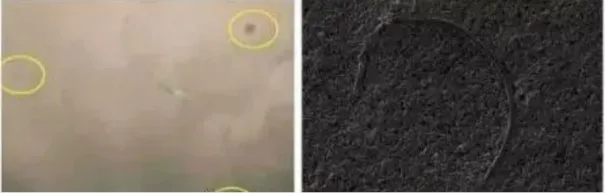
The left picture is the negative electrode plate with bubbles, and the right picture is a 200x magnification of the scanning electron microscope. During the slurry mixing, transfer and coating processes, foreign matter such as dust or long lint is mixed into the coating liquid or falls on the surface of the wet coating, where the surface tension of the coating is affected by external forces, resulting in intermolecular forces. Changes occur, the slurry is slightly transferred, and after drying, circular traces are formed with a thin middle.
- Pinhole
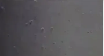
One is the generation of bubbles (stirring process, transportation process, coating process); pinhole defects caused by bubbles are relatively easy to understand. The bubbles in the wet film migrate from the inner layer to the film surface and burst on the film surface to form pinhole defects. Bubbles mainly come from poor fluidity and leveling of the paint during stirring, coating liquid transportation, and coating processes, and poor bubble release from the paint.
- Scratches
- Thick edges
The reason for the thick edge is that the surface tension of the slurry causes the slurry to migrate to the uncoated area on the edge of the electrode sheet, forming a thick edge after drying.
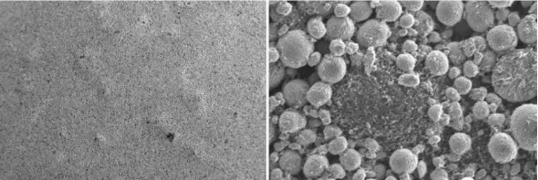
- Negative surface aggregate particles
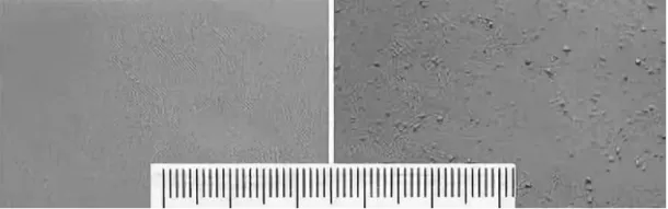
Formulation: Spherical graphite + SUPER C65 + CMC + Distilled water
Macroscopic appearance of two different electrode films using different mixing processes: Smooth surface (left) and surface with numerous small particles (right).
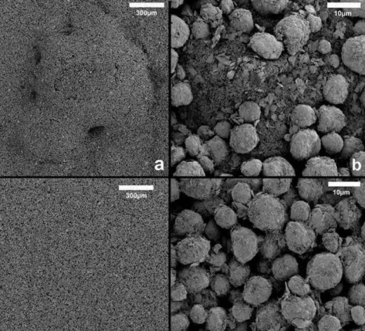
Formulation: Spherical graphite + SUPER C65 + CMC/SBR + Distilled water
Magnified morphology of electrode film surface with small particles (a and b): Aggregation of conductive additives, incomplete dispersion.
Magnified morphology of smooth surface electrode film: Conductive additives are well dispersed and evenly distributed.
- Positive electrode surface aggregate particles
Formulation: NCA+acetylene black+PVDF+NMP
During the stirring process, the ambient humidity was too high, causing the slurry to be in a jelly state, the conductive agent was not completely dispersed, and there were a large number of particles on the surface of the electrode sheet after rolling.
- Water system electrode sheet cracks
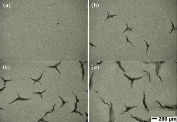
Formulation: NMC532/carbon black/binder = 90/5/5 wt%, water/isopropyl alcohol (IPA) solvent.
Optical photographs of cracks on the electrode film surface at different coating areal densities: (a) 15 mg/cm2, (b) 17.5 mg/cm2, (c) 20 mg/cm2, and (d) 25 mg/cm2. Thicker electrode films are more prone to cracking.
- Shrinkage cavities on electrode sheet surface

Formulation: flake graphite+SP+CMC/SBR+distilled water
There are pollutant particles on the surface of the foil, and there is a low surface tension area in the wet film on the surface of the particles. The liquid film migrates radially around the particles, forming shrinkage point defects.
- Scratches on the surface of the electrode sheet

Formulation: NMC532 + SP + PVdF + NMP
During the slit extrusion coating process, the presence of large particles on the cutting edge leads to foil scratches on the surface of the electrode sheet.
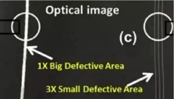
- Coating vertical strips

Formulation: NCA + SP + PVdF + NMP
During the later stages of transfer coating, the slurry exhibits increased viscosity due to water absorption. The coating process approaches the upper limit of the coating window, resulting in poor leveling of the slurry and the formation of vertical streaks.
- Rolling cracks in the wet area of the electrode sheet
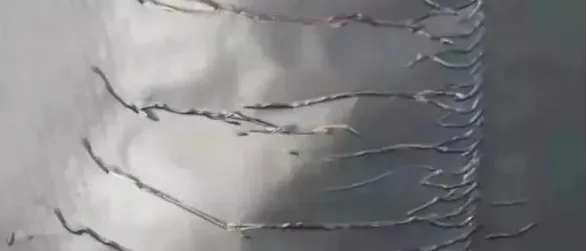
Formulation: flake graphite+SP+CMC/SBR+distilled water
During coating, the middle area ofthe electrode sheet was not completely dry, and the coating migrated during rolling, forming strip-like cracks.
- Electrode sheet rolled edge wrinkles
Thick edges are formed during coating. Rolling type causes wrinkles at the edges of the coating.
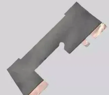
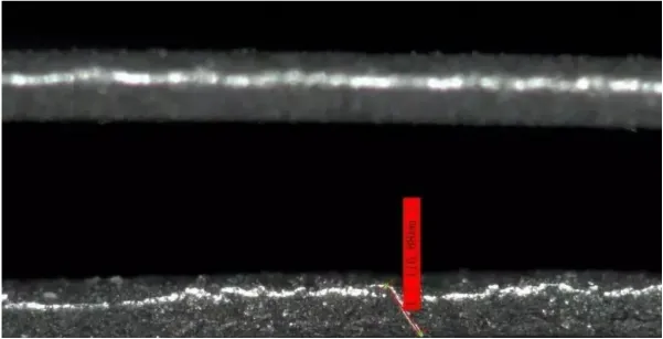
- The negative electrode slitting coating is separated from the foil
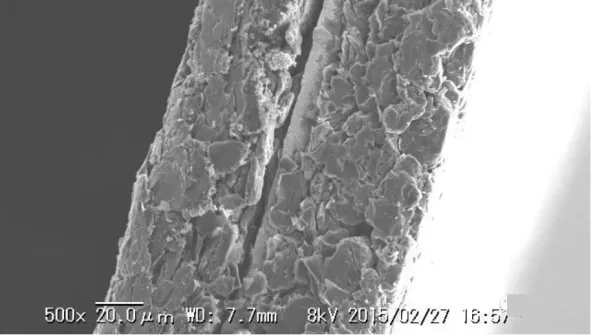
Formula: natural graphite + acetylene black + CMC/SBR + distilled water, active substance ratio 96%
When the electrode sheet disc is slit, the coating separates from the foil.
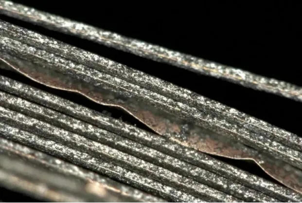
- Electrode sheet slitting burrs
When the positive electrode disc is slit, the unstable tension control causes foil burrs to be formed by secondary cutting.
- Electrode sheet slit wavy edge
When the negative electrode disc is cut, due to improper overlap and pressure of the cutters, wavy edges are formed and the coating of the cut is peeled off.
- Other common coating defects include: air infiltration, transverse waves, vertical flow, Rivulet, expansion, water ripples, etc.
Defects can occur at various stages of the processing: formulation of the coating, preparation of the substrate, coating operation area, drying zone, cutting, slitting, calendering processes, and so on. The general logical approach to resolving defects is as follows:
Optimize the product formulation, coating, and drying processes from pilot-scale to production. Find the optimal or wider process window by adjusting parameters and variables.
Implement quality control measures and statistical tools (such as Statistical Process Control, SPC) to control product quality. Utilize online monitoring systems to ensure stable coating thickness or employ visual inspection systems (Visual Systems) to detect surface defects.
When defects occur, make timely adjustments to the process to avoid recurring defects. Identify the root cause, analyze the process variables, and modify the parameters accordingly to rectify the issue.
4. Uniformity of coating
The term “coating uniformity” refers to the consistency of coating thickness or adhesive distribution within a coating area. The better the consistency of coating thickness or adhesive distribution, the higher the coating uniformity, and vice versa. There is no standardized metric for coating uniformity, but it can be measured by the deviation or percentage deviation of the coating thickness or adhesive amount at various points within a certain area relative to the average coating thickness or adhesive amount in that area. It can also be measured by the difference between the maximum and minimum coating thickness or adhesive amount within a certain area. Coating thickness is typically expressed in micrometers (µm).
Coating uniformity is used to evaluate the overall coating quality within a specific area. However, in practical production, we are usually more concerned about the uniformity in the transverse (cross-machine) and longitudinal (machine direction) directions of the substrate. The transverse uniformity refers to the uniformity in the width direction of the coating (or machine direction), while the longitudinal uniformity refers to the uniformity in the length direction of the coating (or substrate travel direction).
The magnitude, influencing factors, and control methods of transverse and longitudinal coating errors are significantly different. Generally, the wider the substrate (or coating) width, the more challenging it is to control transverse uniformity. Based on years of practical experience in coating operations, it is usually relatively easy to ensure transverse uniformity when the substrate width is below 800mm. When the substrate width ranges from 1300mm to 1800mm, transverse uniformity can often be well controlled but requires a considerable level of expertise. However, when the substrate width exceeds 2000mm, achieving transverse uniformity becomes extremely challenging, and only a few manufacturers can handle it effectively. On the other hand, as the production batch size (i.e., coating length) increases, longitudinal uniformity may become a greater challenge or difficulty compared to transverse uniformity.


