


Coating technology is a process based on the study of fluid properties, which involves applying one or multiple layers of liquid onto a substrate. The substrate is typically a flexible film or paper. The liquid coating is then dried or cured using methods such as oven drying to form a layer with special functionality, such as in the case of lithium-ion battery electrode coating. Currently, the main methods for coating lithium-ion battery electrodes are comma roll transfer coating and slot die extrusion coating.
01 Principle and classification of coating machine
The principle of electrode coating equipment involves the uniform mixing of materials required for the positive or negative electrode formulation, followed by the application or lamination onto the front and back sides of aluminum foil or copper foil. If necessary, an electromechanical integrated device can be used to achieve the customer’s technical requirements by evaporating the solvent from the slurry through energy conduction.
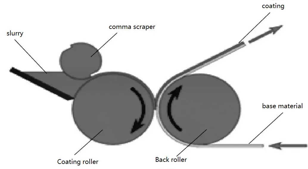
By adjusting the gap between the coating roller and the comma blade, the slurry is metered onto the coating roller. Then, by adjusting the gap between the back roller and the coating roller, the entire metered slurry on the coating roller is transferred onto the foil.
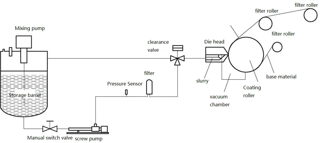
This is a device for high-precision metered coating, which evenly applies Newtonian or non-Newtonian fluid slurries onto the surface of a substrate through a metering pump and a slot die. The formula for calculating the coating thickness is as follows:
Coating Thickness = Metering Pump Flow Rate / (Coating Width * Coating Speed)
In addition, the die is a crucial component of the slot die coating method and is one of the key factors determining coating precision. As coating speeds increase, some customers are now using vacuum chamber mechanisms to ensure coating quality during high-speed coating processes. Typically, when the coating speed is ≥30m/min, the structure of this negative pressure chamber needs to be considered.
The design of the die should consider the following factors:
Calculation and simulation of the flow channel cavity based on the rheological parameters of the slurry.
Requirements for the flatness and straightness of the upper and lower die lips.
Material selection for the die, preferably using stainless steel.
Prevention of the generation of metallic foreign particles during use. If unavoidable, proper protection should be implemented to prevent foreign particles from entering the slurry.
Ease of disassembly and cleaning.
Principle of Dry Method Electrode Preparation (as shown in the diagram):
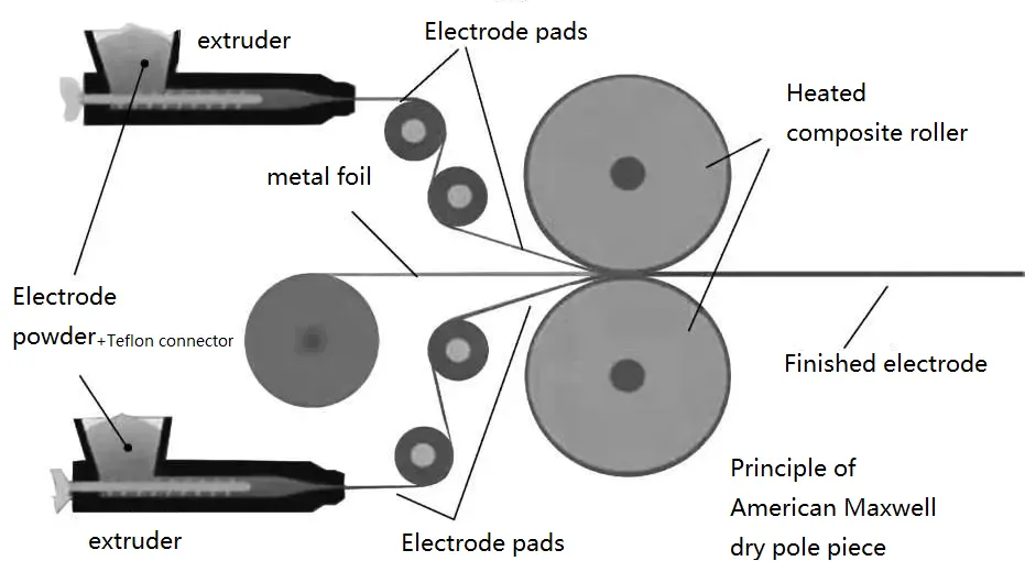
Coating technology has the potential to be a disruptive innovation, especially when combined with solid-state battery technology, to meet the needs of future advanced lithium batteries. For example, the combination of sulfide solid-state electrolytes and dry method electrode technology holds great promise. The advantages of this technology are as follows:
It can meet the stringent environmental requirements in Europe, making the production process environmentally friendly.
It ensures safety during production. Traditional lithium battery cathode coating slurries use NMP (N-Methyl-2-pyrrolidone) as a solvent, which has poor safety characteristics.
The equipment investment cost is low, and it requires a smaller footprint with reduced environmental humidity requirements.
It enables the production of thicker electrode films, which allows for the same volumetric energy capacity while saving on foil and separator materials. This provides significant advantages in terms of Bill of Materials (BOM) cost.
02 Equipment composition and key structure
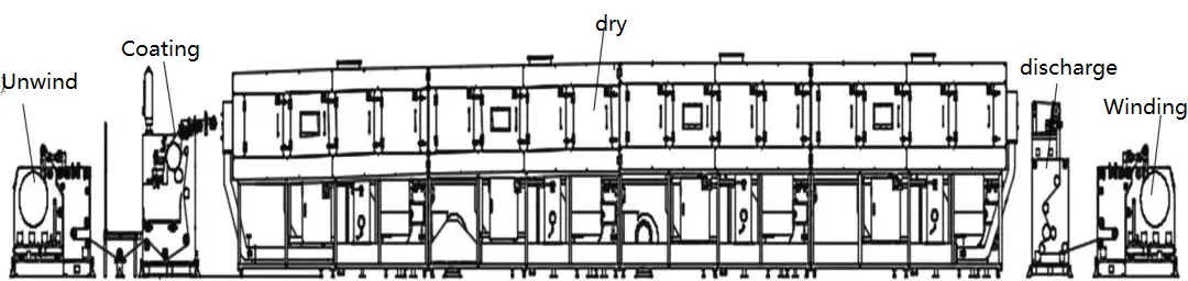
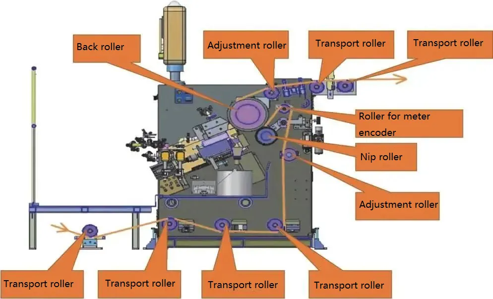
The equipment consists of five main parts: unwinding unit, coating unit (including feeding system), drying unit, discharge unit, and winding unit. The configuration of the coating machine unit is as shown in the diagram.
2.1 Unwinding unit
There are two unwinding methods: automatic tape splicing and manual tape splicing. The manual tape splicing and unwinding unit is shown in the figure.
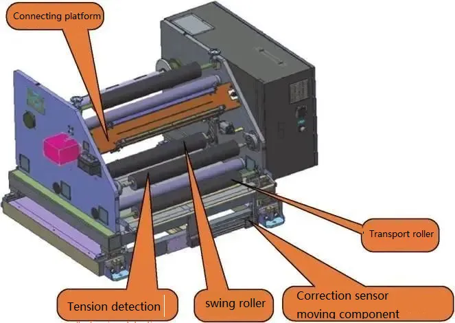
The material to be processed is installed on the unwinding shaft and is guided into the coating section after undergoing edge alignment and tension control. The main control points of the device are unwinding edge alignment and tension control.
Edge alignment is achieved by a dedicated Edge Position Control (EPC) unit. An ultrasonic position detection sensor (capable of detecting transparent films) continuously monitors the position of the material’s edge. The unwinding device is driven by a motor to move left or right, ensuring a constant relative position between the material’s edge and the edge alignment sensor.
There are three modes of edge alignment: fully automatic, where the system automatically engages edge alignment upon power-up (based on the sensor’s feedback to drive the motor); semi-automatic, where the system engages edge alignment during automatic operation (coating and traction), and manual edge alignment during stoppage; and manual mode, where the edge alignment mechanism can only be operated manually regardless of the system’s status.
Tension control consists of two parts: floating roller position control and actual tension detection control. The principle of floating roller position control is as follows: during automatic operation, the PLC controller adjusts the speed of the unwinding shaft motor using a PID algorithm based on the real-time feedback signal (0% to 100%) from the potentiometer, aiming to maintain a constant floating roller position (default position is set at 50%).
2.2 Coating unit and feeding and intermittent valve system
(1) Coating unit
After the material is fed into the coating roller from the unwinding unit, it passes through the feeding pressure roller for tension isolation (separating the tension between unwinding and discharge) and then goes through the coating roller before being guided into the drying furnace. The main control points of this device are the stability of the overall machine speed and the gap value between the die and the backing roller.
The displacement between the die and the backing roller is driven by two parts. The large-scale movement is achieved through cylinders (forward and backward), while precise positioning is driven by servo motors on the left and right sides (actual displacement detected by high-precision linear encoders with a resolution of 0.1 μm).
(2) Feeding System
The feeding system includes a material storage tank, metering pump, iron remover, filter, and connected pipes. Initially, the slurry is added to the storage tank. Once the coating starts, the slurry in the storage tank is pumped through the connected pipes, iron remover, and filter into the slot die for coating. When the level sensor detects that the slurry in the storage tank reaches the specified level, feeding to the storage tank begins. When the slurry reaches the designated level, the level sensor sends a command to stop feeding the storage tank.
2.1 Drying unit
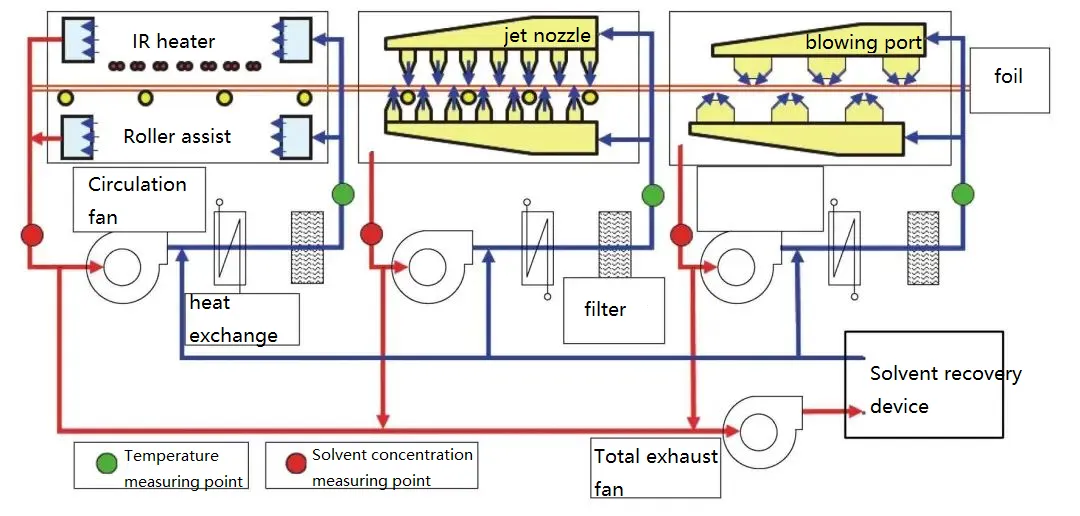
The schematic diagram of drying principle is shown in the figure
The slurry containing liquid solvent components, produced by the coating unit, enters the drying furnace together with the film. To safely and effectively evaporate the solvent, it is necessary to control the temperature, air supply, exhaust volume, and other parameters in each section of the drying furnace. The single-section temperature control system consists of heating elements and circulating fans. The fans are driven by variable frequency motors, and the air volume and velocity can be adjusted by setting the frequency (which is directly proportional to the frequency). The heating temperature is maintained through constant control based on temperature changes at temperature control points detected by sensors, ensuring the quality of the drying process.
2.2 Discharging unit
After drying, the film enters the discharge device. The discharge device controls the tension and edge position of the film within the drying furnace. The main control points of this device are edge alignment and tension control in the drying area.
Edge alignment is similar to the unwinding unit, utilizing a dedicated Edge Position Control (EPC) system. An edge position detection sensor continuously monitors the position of the film’s edge, and the discharge device adjusts its position to maintain a constant relative position between the film’s edge and the edge alignment sensor.
2.3 Rewinding unit
There are two methods for winding: automatic winding and manual winding.
After the completion of production, the finished film passes through edge alignment and tension control before being guided onto the winding shaft. The main control points of this device are edge alignment and tension control during the winding process, which are similar to the unwinding unit.
During the winding process, to prevent slippage between layers and avoid excessive tightness or core pulling, it is necessary to adjust the winding tension taper.
03 Equipment selection
3.1 Equipment selection principles
(1) Safety First:
Due to the presence of NMP organic solvent in our coating machine, strict explosion-proof requirements must be met, in accordance with the industry standard “Design Standard for Lithium-ion Battery Factories” (GB 51377-2019).
(2) Ensuring Battery Safety and Preventing Foreign Metal Contamination:
During the production process of lithium-ion batteries, it is crucial to prevent the introduction of foreign metal particles. Therefore, components that come into contact with the slurry and electrode sheets or are in close proximity to them should not be made of copper, zinc, or tin.
(3) Selection of Equipment and Parameters:
Currently, the slot die coating method is primarily used.
(4) Selection of Coating Die:
① Since the battery slurry is a non-Newtonian fluid, rheological parameter testing is necessary. Specialized rheometers are typically used to determine these parameters. The coating die’s flow channel shape should be designed based on the calculated rheological parameters and simulation results to ensure coating accuracy.
② It is recommended to install the coating die at an upward angle of 25°. This allows for quick air release from the pipelines and cavities after cleaning the die and prevents the use of a die return flow pipe as a substitute for air exhaust function.
(3) Selection of Feed Pump:
Typically, a high-precision metering screw pump is used. The pump’s specifications and model are selected based on the required flow rate. To improve pumping accuracy, a dual-pump structure is recommended, which reduces pulsation and ensures high precision.
(4) Selection of Drying Furnace:
① Overall Length and Length of Each Section:
First, determine the length of each section of the drying furnace. It is recommended that the length of each section should not be less than 4m. The faster the drying speed, the longer the section length should be. However, considerations should be given to transportation and assembly feasibility. The maximum length of each section is recommended not to exceed 5m. The determination of the overall length of the drying furnace is based on the drying process and coating speed parameters, which are typically provided by the user. The equipment manufacturer then meets these process requirements.
② Temperature Range for Drying in the Furnace:
The recommended temperature range is from room temperature to 140°C. If there are specific process requirements, customization can be considered. Generally, the maximum temperature should not exceed 160°C.
③ Range of Drying Air Velocity in the Furnace:
A range of 5 to 20m/s is recommended, with nozzle accuracy within ±20%.
(5) Substrate Transportation in the Drying Furnace:
① For copper/aluminum foil substrates with a thickness greater than 6-10μm, it is recommended to use a combination of active guide rollers and a floating drying furnace.
② For copper/aluminum foil substrates with a thickness less than 6-10μm, due to reduced tensile strength, it is recommended to use active guide rollers.
Selection of Winding Diameter:
Since the unwinding diameter is matched based on the incoming material diameter, I won’t provide detailed explanation here. However, there are techniques for selecting the winding diameter. It is recommended to determine the length of the large roll based on the cumulative length of individual electrode sheets obtained from slitting or die-cutting, and then convert it into a winding diameter. The calculation formula is as follows:
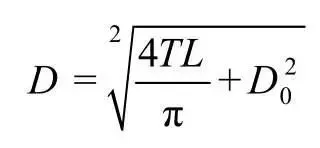
In the formula, D is the diameter of the coil; D0 is the diameter of the bottom cylinder; T is the thickness of the electrode sheet; L is the length of the electrode sheet .
Only in this way can the utilization rate of materials be increased, waste reduced, and costs reduced. Due to the improvement in automation, according to the formula, it can be seen that increasing the diameter of the bottom cylinder can better increase the length of the entire roll of electrode sheet, and at the same time reduce the pressure of the bottom electrode sheet. Improve winding quality.


