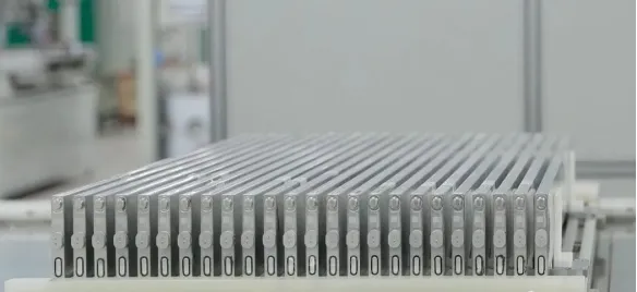

Lithium Battery Top 10 Key Equipment – calendering Machine
Oct 5, 2023


Follow me on:
01 Functions, principles and influencing factors of rolling quality of calendering machine
- Functions of calendering machine
Calendering is a process in which the coated and partially dried lithium battery electrode sheets are compacted. Calendering of electrode sheets increases the energy density of lithium batteries and ensures that the electrode materials are firmly attached to the current collector, preventing the loss of battery energy caused by detachment during cycling. Prior to calendering, the coated electrode sheets need to be dried to a certain degree to prevent the coating from peeling off during compaction. It is also important to control the compaction level during the process. Excessive compaction can affect the electrode materials near the current collector, hindering the proper insertion and extraction of lithium ions and causing the active materials to tightly adhere together, leading to easy detachment from the current collector. In severe cases, excessive plasticity of the electrode sheets can result in breakage and hinder the winding process after compaction. Calendering is one of the most critical processes in the manufacturing of lithium battery electrodes, and its precision significantly impacts battery performance. The objectives of calendering include maintaining a smooth and flat surface of the electrode sheets to prevent potential short circuits caused by protrusions puncturing the separator, and improving the energy density of the batteries. The compaction process also reduces the volume of the electrode sheets, thereby enhancing the energy density, cycle life, and safety performance of lithium batteries.
- Principle of electrode sheet calendering
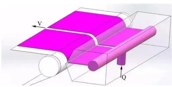
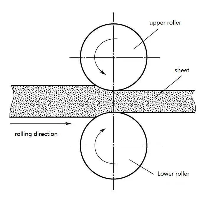
The purpose of calendering is to achieve a denser and more uniformly bonded connection between the active material and the foil. The roller compaction process should be carried out after the coating is completed and the electrode sheets are dried. Otherwise, issues such as powder shedding and layer delamination may occur during compaction. The battery electrode sheets consist of copper (or aluminum) foil coated on both sides with electrically conductive paste particles. After undergoing the coating and drying processes, the electrode sheets are subjected to roller compaction. Prior to compaction, the coating of electrically conductive paste on the copper (or aluminum) foil is a semi-fluid, semi-solid granular medium composed of individual or weakly connected particles or clusters, exhibiting certain dispersibility and flowability. There are gaps between the electrically conductive paste particles, which ensures that during the compaction process, the particles can undergo small displacements to fill the gaps and achieve mutual positioning under compaction. Calendering of battery electrode sheets can be considered as a continuous compaction process of semi-solid electrically conductive paste particles in an unsealed state. The electrically conductive paste particles adhere to the copper (or aluminum) foil’s surface, continuously being drawn into the gap between the rollers by frictional force, and compacted into electrode sheets with a certain density. The principle of calendering is illustrated in Figure 2.
The rolling of battery electrode sheets differs significantly from the rolling of steel. When steel is rolled, the workpiece undergoes elastic deformation initially when subjected to external forces. When the external force reaches a certain limit, the workpiece begins to experience plastic deformation. As the external force increases, the plastic deformation increases. The purpose of longitudinal rolling in steel rolling is to obtain elongation. During the steel rolling process, the molecules extend longitudinally and expand laterally, resulting in a reduction in the thickness of the workpiece without a change in density.
On the other hand, battery electrode sheets involve the application of compound slurry onto substrates such as aluminum foil or copper foil. The roller compaction of electrode sheets aims to compact the electrically conductive paste particles on the sheets. Its purpose is to increase the compacted density of the electrode sheets. The appropriate compacted density can enhance the battery’s discharge capacity, reduce internal resistance, and extend the battery’s cycle life. The electrically conductive paste particles undergo displacement and deformation when subjected to pressure during the compaction process. The density of the electrode sheet follows a certain pattern with the variation of pressure, as shown in Figure 3.
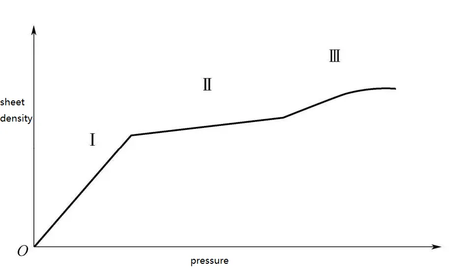
In Region I, as the contact pressure increases, the electrically conductive paste particles begin to undergo small-scale displacement, which gradually increases. At this stage, the gaps between the paste particles are gradually filled, resulting in a slow increase in the relative density of the electrode sheet.
In Region II, after the density of the paste particles has been slightly increased in Region I, further increase in contact pressure leads to continued filling of the gaps between the particles. As the compaction progresses in Region II, the gaps between the particles are fully compressed, resulting in a rapid increase in the relative density of the electrode sheet. The rate of increase in relative density is much higher than that in Region I, and some deformation of the paste particles occurs in this region.
In Region III, after the gaps between the paste particles have been completely filled in Region II, the particles no longer undergo displacement. However, as the contact pressure increases, the paste particles begin to undergo significant deformation. At this stage, the relative density of the electrode sheet does not increase rapidly with increasing contact pressure. Instead, the electrode sheet undergoes hardening, and the change in relative density becomes a gentle curve.
- Factors affecting rolling quality
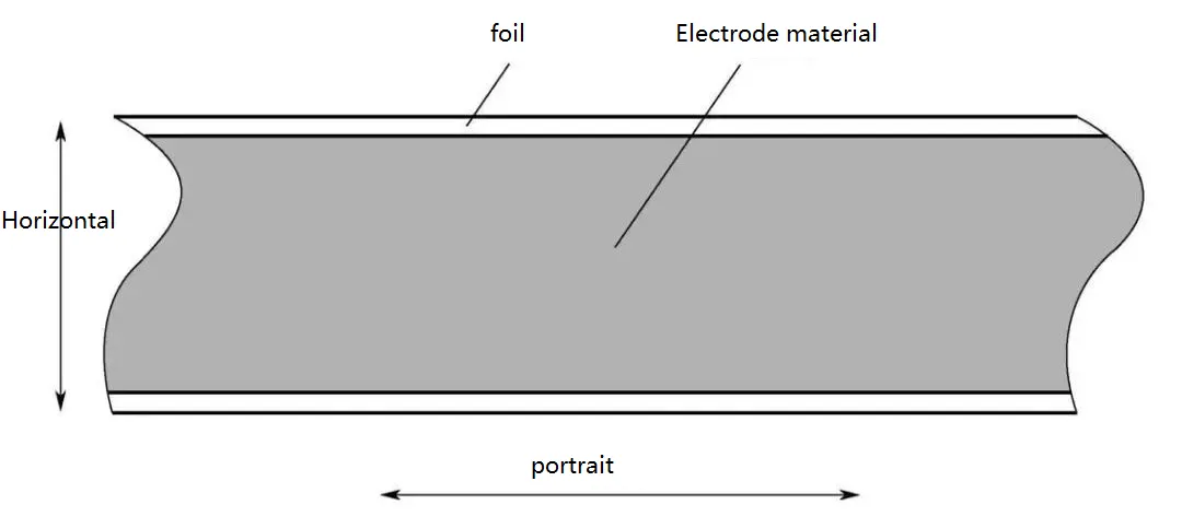
The quality issues of battery electrode sheets caused by calendering machine mainly manifest in the uneven thickness of the sheets after rolling. The inconsistency in thickness leads to variations in the compacted density of the electrode sheets, which is a critical factor affecting battery performance consistency. The uniformity of electrode sheet thickness includes both transverse thickness uniformity and longitudinal thickness uniformity, as shown in Figure 4, and they have different causes.
The main factors influencing the transverse thickness non-uniformity of the electrode sheet include the bending deformation of the rolling rolls, the rigidity of the machine frame, the elastic deformation of the main stress-bearing components, the compaction force, and the width of the sheet. During the operation of the calendering machine, the compaction force causes deformation in the rolling rolls and the machine frame, ultimately resulting in deflection deformation of the rolls. This leads to the phenomenon of the sheet being thicker in the middle and thinner on the sides in the transverse direction.
The main factors influencing the longitudinal thickness non-uniformity of the electrode sheet include the processing accuracy and installation precision of the rolling rolls, bearings, and bearing seats. The machining errors of critical components can cause periodic fluctuations in the compaction force applied to the sheet as the rolls rotate, resulting in non-uniform compacted thickness in the longitudinal direction of the sheet.
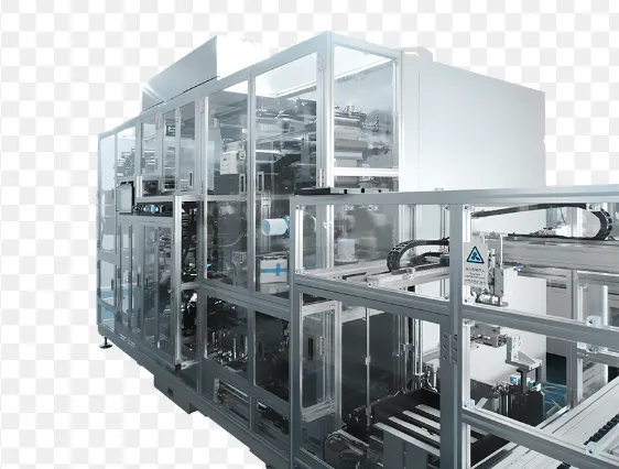
02 Structural composition and classification of calendering machine
2.1 Basic structure of calendering machine
The standard configuration of a high-precision calendering machine for battery electrode sheets consists of a vertically mounted H-shaped frame, with two rolls arranged horizontally, and a hydraulic cylinder mounted below applying pressure upwards. The roll gap is adjusted by a servo motor reducer, and the machine is mounted on an integral base. The dual output shafts of the reducer are connected to the speed reducer through a universal coupling. This configuration ensures high precision in the calendering process. The schematic diagram of the standard model calendering machine is shown in Figure 5.
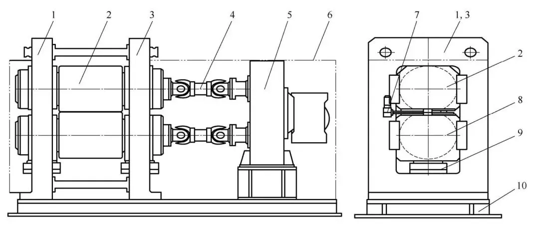
1—Left frame; 2—Upper roll system; 3—Right frame; 4—Universal coupling; 5—Dual output shaft speed reducer; 6—Cover; 7—Roll gap adjustment mechanism; 8—Lower roll system; 9—Hydraulic cylinder; 10—Base.
As shown in Figure 5, the calendering machine mainly consists of the frame, rolls, and main transmission components. The frame serves as the foundation of the entire system and needs to have sufficient rigidity and strength to minimize deformation. The hydraulic device applies the compaction force to the rolls through the bearing seats. The motor and reducer enable synchronous rotation of the two rolls, providing torque to the rolls and ensuring continuous calendering process. The roll gap adjustment mechanism consists of two gap adjustment wedges, which are used to adjust the gap between the two rolls to meet the thickness requirements of different electrode sheets.
2.2 Structural form of main machine of calendering machine
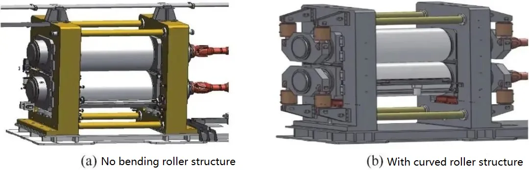
① Classification based on roll type. The main rolls of the calendering machine can be divided into two forms: curved rolls and straight rolls, as shown in Figure 6. The structure with straight rolls (standard model) has a bearing seat with internal mechanisms to eliminate the radial clearance of the main bearings and provide axial positioning. The structure with curved rolls uses a curved roll cylinder to eliminate the radial clearance of the main bearings and reduce or eliminate the deflection deformation of the roll surface.
When the width of the compacted electrode sheet is relatively narrow, the ratio of the roll surface width to the roll surface diameter is close to 1:1, and the deflection deformation during the compaction of the electrode sheet can be neglected, it is recommended to use the standard model without curved rolls.
When the width of the compacted electrode sheet is relatively wide, the ratio of the roll surface width to the roll surface diameter is greater than 1.2:1, and the deflection deformation during the compaction of the electrode sheet is greater than 0.5μm, it is recommended to use a model with curved rolls.
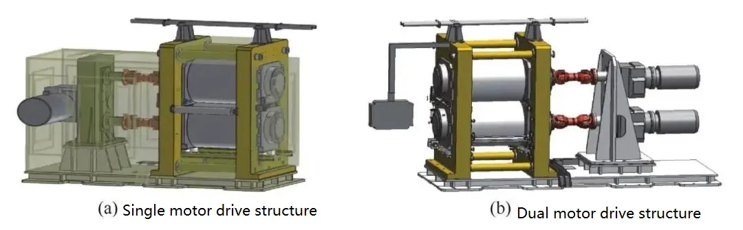
② Classification based on driving mode. The roller compaction machine can be categorized into single-motor driving structure and dual-motor driving structure, as shown in Figure 7.
The single-motor driving structure utilizes a driving motor, reducer, speed reducer, universal coupling, and roll transmission to achieve mechanical synchronization of the rolls through the speed reducer.
The dual-motor driving structure adopts a driving motor, reducer, universal coupling, and roll transmission. It employs synchronous motors controlled by electronics to achieve mechanical synchronization of the rolls.
The driving torque of the calendering machine is proportional to the calendering speed, roll surface width, and inter-roll pressure. When the roll surface width and pressure remain relatively constant, a higher speed requires a greater driving torque and a larger motor power. In cases where high speed and significant motor power are required, the calendering machine can be driven by two synchronous motors.
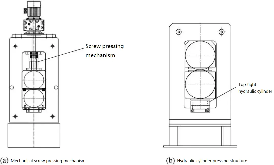
③ Classification based on pressing method. The roller compaction machine can be divided into mechanical screw tightening structure and hydraulic cylinder tightening structure, as shown in Figure 8.
The mechanical screw tightening structure primarily applies pressure to the rolls on the electrode sheet by setting the roll gap value. It does not require additional pressurization devices. Therefore, the actual pressure is generally relatively small, limiting the compaction density of the electrode sheet during roller compaction.
The hydraulic cylinder tightening structure involves mounting hydraulic cylinders below the bearing seats at both ends of the lower roll system, inside the V-shaped frame. The hydraulic cylinders use plunger cylinders to push upward and apply pressure. Under the action of the plunger cylinders, the lower roll system moves upward and exerts roll compaction pressure. By applying pressure using the hydraulic cylinders, stable pressure can be achieved, and higher pressures can be exerted. This method is currently the mainstream pressing method used.
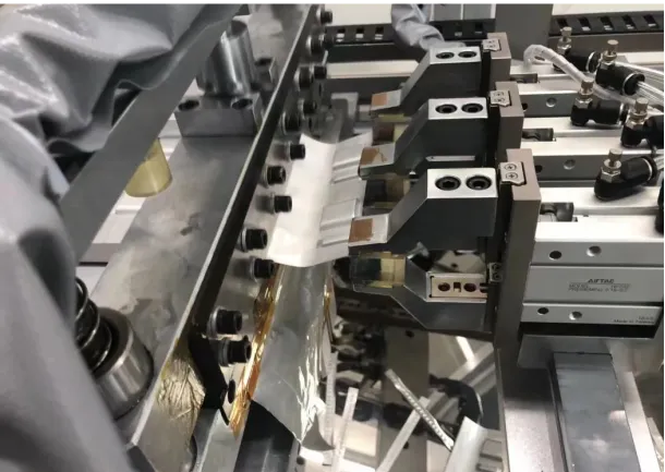
2.3 In China, most of the calendering machines for lithium battery electrode sheets perform compaction at room temperature. During the compaction process, the electrode sheet exhibits significant rebound, so it is beneficial to preheat the electrode sheet to a certain temperature before compaction. The purpose of preheating is as follows: to dry the electrode sheet and reduce its moisture content, to reduce the rebound rate of the electrode sheet after compaction, to eliminate some of the residual internal stress in the electrode sheet after compaction, and to soften or melt the binder on the electrode sheet surface through heating, which enhances the adhesion between the active material and the current collector, facilitating better electrolyte absorption. To heat the electrode sheet, a heating box is installed before the roller compaction machine to heat the electrode sheet. The air inside the heating box is heated, and then the heated air is used to heat the electrode sheet. However, this method has low heating efficiency because of the distance between the heating box and the rolls, resulting in rapid heat loss and ineffective heating. Currently, the widely used method is the hot calendering machine, where the rolls of the machine are heated first, and then the heated rolls are used to compact the lithium battery electrode sheet. The heating of the rolls can be achieved through external heating or internal heating, and several common heating methods are described as follows:
① External heating of the rolls using electromagnetic induction. Induction coils are placed outside the rolls. When the coils are energized, electromagnetic induction generates eddy currents inside the rolls, thereby heating the rolls. This heating method has the advantages of low energy consumption, high thermal conversion rate, and precise control of the roll surface temperature during compaction. However, it also has some drawbacks, such as high cost and difficulties in arranging wiring along the circumference of the rolls.
② Heating the rolls using an external heating box. The heating box is positioned above or below the rolls, and high-temperature air is used to bake the rolls from the outside. Heat is transferred to the working surface of the rolls through air as the heat transfer medium, achieving the purpose of heating the rolls. However, this method has serious issues: it is difficult to control the temperature of the roll surface, the temperature distribution on the roll surface is uneven, localized high temperatures can damage the rolls, and it consumes a large amount of energy with significant energy loss.
③ Heating the rolls from the inside using electronic components such as resistance wires. Typically, tubular heating elements or resistance wires are inserted into the internal part of the working rolls or support rolls. By connecting one end of the rolls to a power source, the rolls are heated. This heating method has the advantages of not damaging the external structure of the rolls, simplicity, and ease of implementation. The heating process starts from the roll core, and the heat is conducted from the core to the working surface of the rolls, resulting in an intermediate-first heating approach. However, this method increases the thermal stress on the rolls during the heating process. For larger diameter rolls, the heat transfer time is long, making it less sensitive to adjusting the roll surface temperature and requiring longer adjustment cycles. Additionally, localized high temperatures occur at the bearing positions, causing difficulties in lubrication.
④ Heating the rolls using heat transfer oil. Heating the rolls with heat transfer oil is a widely used method both domestically and internationally. Internal oil passages are created within the rolls, and heated heat transfer oil is introduced into the rolls through rotary joints, heating the rolls through thermal conduction. Heat transfer oil can operate stably at temperatures up to 200°C. This method is safe, environmentally friendly, and has low noise. The heat transfer oil circulation system has high temperature precision, making it easy to control the inlet temperature of the heat transfer oil. By controlling the flow rate of the heat transfer oil at the inlet, forced convection heat transfer occurs between the heat transfer oil and the rolls, increasing the convective heat transfer coefficient between them and maximizing the heat transfer between them. This ensures that the roll surface maintains a constant temperature range and has good uniformity, meeting the temperature requirements for most rolls.