Lithium Battery Top 10 Key Equipment – Injection Equipment
Oct 17, 2023


Follow me on:
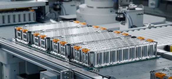
One of the key processes in the commercialization of secondary lithium-ion batteries is the use of liquid electrolytes, making the injection process essential. The injection process refers to the procedure of injecting electrolyte into the interior of the battery cell and sealing it using injection equipment.
01.Overview of Injection Equipment
1.1 Importance of Injection Equipment
In the manufacturing process of secondary lithium-ion batteries, the role of the electrolyte is to facilitate the conduction of ions between the positive and negative electrodes. It acts as a medium for the transport of lithium ions, similar to how blood in our lungs facilitates the exchange of oxygen and carbon dioxide. This highlights the importance of the electrolyte within the entire battery system.
Typically, a common lithium-ion battery electrolyte consists of inorganic lithium salt electrolyte, organic carbonate solvents, and additives. As a medium for lithium ion migration and charge transfer, the electrolyte is an indispensable and crucial component of a lithium-ion battery. It forms the foundation for the battery to achieve advantages such as high voltage, high energy density, and high cycling performance.
The most critical parameters for assessing battery injection are the injection volume, wetting effect (thorough and uniform), and injection accuracy. These three aspects are achieved through the performance of the injection equipment. Therefore, the injection equipment is crucial in the production process of lithium-ion batteries as it directly impacts battery performance. The main parameters of the equipment are described as follows:
① Injection Volume: It is necessary to consider meeting the design requirements of the battery and ensuring that the specified amount of electrolyte is fully injected into the battery. The injection volume needs to be accurately controlled to ensure that the electrolyte quantity inside each battery cell meets the requirements.
② Wetting Effect: The wetting effect refers to the uniform infiltration of the electrolyte into the interior of the battery electrodes, allowing the electrodes to exhibit optimal electrochemical performance. Incomplete wetting can adversely affect the performance consistency of the battery. Achieving the best wetting effect in the shortest possible time is a crucial aspect of the injection equipment’s process capability.
③ Injection Accuracy: Injection accuracy reflects the consistency of the electrolyte quantity in the battery, which in turn affects the performance consistency of the battery. It also reflects the performance and capability of the injection equipment.
In addition to fulfilling the aforementioned three points to meet the requirements, the injection equipment also needs to consider employing the optimal injection process to achieve the desired outcome in the fastest time possible, with minimal injection cycles, minimal space requirements, minimal manual intervention, and minimal costs.
1.2 Principle of injection equipment
The principle of injection equipment is to inject the electrolyte into the limited internal cavity of the battery (which includes the cell and the unfilled space) using a specific process (such as vacuum, pressure, and time). A portion of the electrolyte infiltrates into the battery cell (consisting of positive and negative electrode sheets and a separator), while another portion occupies the unfilled space. The total amount of electrolyte injected is referred to as the injection volume. The better the wetting effect is, the more electrolyte infiltrates into the battery cell. The shorter the time taken to infiltrate the electrolyte into the battery cell, the better the process capability of the injection equipment.
The deviation between the actual injection volume and the set injection volume for a specific battery represents the injection accuracy. For a batch of batteries, the better the consistency of the injection volume and the more concentrated the injection volume, indicated by a higher CPK value of the injection weight, the better the overall performance of the injection equipment.
1.3 Types of injection equipment
1.Based on Battery Types
① Pouch injection equipment.
② Hard-shell injection equipment, including cylindrical battery injection equipment and prismatic battery injection equipment.
2.Based on Structural Types
①Linear injection equipment, including a reciprocating structure.
② Rotary injection equipment.
Based on Injection Processes
① Vacuum injection equipment, which generally refers to the vacuum and atmospheric pressure breathing infiltration method.
② Low-pressure injection equipment, which typically involves pressure below 0.3 MPa during pressurization and cyclic infiltration with vacuum and pressure alternation.
③High-pressure injection equipment, which generally involves pressure between 0.5 to 0.8 MPa during pressurization and cyclic infiltration with vacuum and pressure alternation. High pressure enables better injection and wetting effects, making it the current development direction of injection equipment. Currently, a significant portion of cylindrical batteries and prismatic aluminum shell batteries (with the support of isostatic pressure) use high-pressure injection. However, high-pressure injection has not been widely adopted for pouch-type batteries.
④ Ultra-high-pressure injection equipment: Currently, there is no clearly mass-produced ultra-high-pressure injection equipment available on the market. In the future, there may be injection equipment with higher static pressure. injection equipment operating with pressurization between 1 to 2 MPa can be referred to as ultra-high-pressure injection equipment. For batteries with higher energy density in the future, there is a possibility of utilizing ultra-high-pressure injection equipment, which would potentially reduce the required post-injection settling time.
4)Based on Pressurization Method
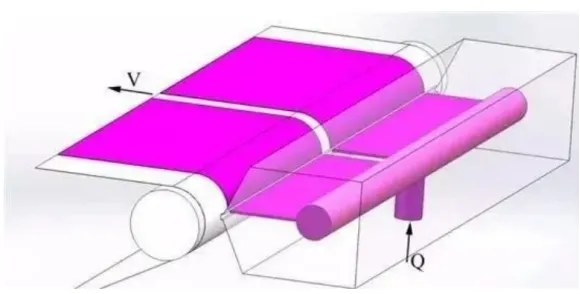
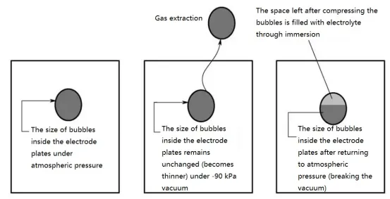
① Differential pressure injection equipment: This generally refers to applying positive pressure only to the internal cavity of the battery during pressurization and static settling. There is a pressure difference between the internal cavity of the battery and the external shell, hence the term “differential pressure” injection or differential pressure settling. It is worth noting that for prismatic hard-shell batteries, due to the presence of explosion-proof membranes and the tendency of the prismatic shell to deform, differential pressure injection equipment is typically of the low-pressure type. For cylindrical batteries such as steel shell 18650/26650 batteries, differential pressure injection equipment can be either low-pressure or high-pressure. The diagram below illustrates the principle of high-pressure-vacuum cyclic injection.
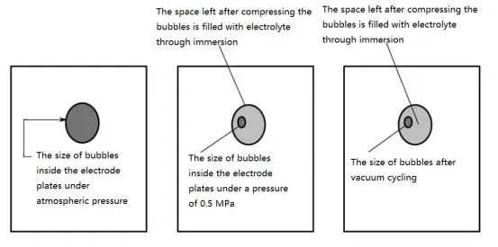
② Isostatic injection equipment generally refers to applying equal positive pressure to both the internal cavity of the battery and the external shell during pressurization and static settling. There is little to no pressure difference between the internal cavity of the battery and the external shell, hence the term “isostatic” injection or isostatic settling. In terms of logical relationship, high pressure is the goal, and isostatic pressure is the means to achieve high pressure. Without the presence of pressure, isostatic pressure is meaningless. Isostatic injection equipment allows prismatic aluminum shell batteries to achieve high-pressure injection. Pouch batteries can also utilize high-pressure isostatic injection. The diagram illustrates the schematic diagram of atmospheric pressure-vacuum cyclic injection.
1.4 injection Machine Functions
① A single injection machine for prismatic aluminum shell power batteries includes the following functions:
a. Material Loading: Manual operation or automatic operation by a robotic arm.
b. Code Reading: Barcodes or QR codes.
c. Pre-weighing: Binding barcodes with weight, with data recorded in the MES system.
d. Tray Placement: Placing batteries into trays and positioning the trays.
e. Leak Testing: Checking the seal of the injection nozzle.
f. injection: Using an injection pump.
g. Settling, Vacuum, and Pressure Cycling Modes: High-pressure mode, low-pressure mode, and isostatic mode.
h. Unloading from Trays: Removing batteries from the trays.
i. Post-weighing: Binding barcodes with weight, with data recorded in the MES system.
j. Sealing injection Holes: Inserting adhesive pins during the insertion process.
k. Material Discharge.
② A secondary injection machine for prismatic aluminum shell power batteries includes the following functions:
a. Material Loading: Manual operation or automatic operation by a robotic arm.
b. Code Reading: Barcodes or QR codes.
c. Pre-weighing: Binding barcodes with weight, with data recorded in the MES system to calculate the amount of secondary injection (variable injection).
d. Tray Placement: Placing batteries into trays and positioning the trays.
e. Leak Testing: Checking the seal of the injection nozzle.
f. injection: Performing variable injection using a variable injection pump.
g. Settling, Vacuum, and Pressure Cycling Modes: High-pressure mode, low-pressure mode, and isostatic mode.
h. Unloading from Trays: Removing batteries from the trays.
i. Post-weighing: Binding barcodes with weight, with data recorded in the MES system.
j. Vacuum Extraction and Helium Backfilling: Negative pressure extraction and backfilling with helium, using sealing adhesive pins.
k. Sealing injection Holes: Inserting adhesive pins during the insertion process.
l. Material Discharge.
③ injection machines for cylindrical 18650/21700/26650 batteries (injecting liquid before sealing the cap) generally include the following functions:
a. Material Loading: Typically automated loading method.
b. Pre-weighing: Binding barcodes with weight, with data recorded in the MES system to calculate the amount of secondary injection (variable injection).
c. Tray Placement: Placing batteries into trays and positioning the trays.
d. Leak Testing: Checking the seal of the injection nozzle.
e. injection: Using an injection pump.
f. Settling, Vacuum, and Pressure Cycling Modes: High-pressure mode, low-pressure mode, and isostatic mode.
g. Unloading from Trays: Removing batteries from the trays.
h. Post-weighing: NG (non-compliant) units are discharged.
i. Material Discharge.
④ injection machines for cylindrical 18650/21700/26650 batteries (sealing the cap before injecting liquid) generally include the following functions:
a. Material Loading: Typically automated loading method.
b. Cap Orientation: Determining the correct orientation of the cap.
c. Pre-weighing: Binding barcodes with weight, with data recorded in the MES system to calculate the amount of secondary injection (variable injection).
d. Tray Placement: Placing batteries into trays and positioning the trays.
e. Sequential injection: Using an injection pump, typically in 5-6 stages of injection.
f. Sequential Settling, Vacuum, and Pressure Cycling Modes: High-pressure mode, low-pressure mode, and vacuum mode.
g. Unloading from Trays: Removing batteries from the trays.
h. Post-weighing: NG (non-compliant) units are discharged.
i. Cap Orientation and Tab Folding: Determining the correct orientation of the cap and folding the tab.
j. Flattening the Cap: Flattening the cap.
k. Material Discharge.
⑤ injection machines for pouch batteries generally include the following functions:
a. Material Loading: Manual operation or automatic operation by a robotic arm.
b. Code Reading: Barcodes or QR codes.
c. Pre-weighing: Binding barcodes with weight, with data recorded in the MES system.
d. Tray Placement: Placing batteries into trays and positioning the trays.
e. Leak Testing: Checking the seal of the injection nozzle.
f. injection: Using an injection pump.
g. Settling: Typically involves vacuum and atmospheric pressure settling cycles.
h. Unloading from Trays: Removing batteries from the trays.
i. Post-weighing: Binding barcodes with weight, with data recorded in the MES system.
j. Sealing injection Holes: Using a heat sealing method.
k. Material Discharge.
⑥ Single-pass injection machines for large cylindrical aluminum shell batteries generally include the following functions:
a. Material Loading: Manual operation or automatic operation by a robotic arm.
b. Code Reading: Barcodes or QR codes.
c. Pre-weighing: Binding barcodes with weight, with data recorded in the MES system.
d. Rotational Alignment of Injection Holes: Typically achieved through CCD recognition.
e. Tray Placement: Placing batteries into trays and positioning the trays.
f. Leak Testing: Checking the seal of the injection nozzle.
g. injection: Using an injection pump.
h. Settling, Vacuum, and Pressure Cycling Modes: High-pressure mode, isostatic mode.
i. Unloading from Trays: Removing batteries from the trays.
j. Post-weighing: Binding barcodes with weight, with data recorded in the MES system.
k. Sealing injection Holes: Inserting adhesive pins during the insertion process.
l. Material Discharge.
1.5 Performance Indicators
1.Injection Efficiency
① Efficiency of cylindrical battery injection machines:
a. Efficiency for 18650/21700/26650 batteries (sealing the cap before injecting liquid): Available options include 80PPM, 120PPM, 200PPM, and 300PPM.
b. Efficiency for 18650/21700/26650 batteries (injecting liquid before sealing the cap): Available options include 80PPM and 120PPM.
c. Efficiency for large cylindrical aluminum shell batteries (outer diameter 32-50mm, height 80-273mm): Currently in production at 50PPM and 72PPM, with potential future options reaching 100PPM or higher.
d. Efficiency for large cylindrical steel shell batteries (outer diameter 32-26mm, height 80-160mm): Currently in production at 60PPM and 120PPM, with potential future options reaching 200PPM or higher. For the 46800 battery with an open steel shell structure, the production line efficiency can be considered in the range of 80PPM, 120PPM, 160PPM, and 200PPM in gradual increments.
② Efficiency of battery injection machines for power batteries with aluminum shells:
a. Efficiency for 26148 batteries: Typically in the range of 12-24PPM, with potential future options in the 24-60PPM range.
b. Efficiency for 50160 batteries: Typically in the range of 12-24PPM, with potential future options in the 24-60PPM range.
c. Efficiency for 33230 batteries: Typically in the range of 12-24PPM, with potential future options in the 24-48PPM range.
③ Efficiency of injection machines for pouch power batteries:
Efficiency of pouch power batteries: Generally in the range of 6-24PPM.
④ injection machines for pouch 3C batteries:
Efficiency of pouch 3C batteries: Typically in the range of 12-24PPM for small pouches.
1.Injection Accuracy
a. Injection accuracy for pouch batteries: Typically around 0.5%.
b. Injection accuracy for 18650 batteries: Generally around ±0.1g, considering the deviation of the weighing system itself, with a set deviation of the weighing software typically around ±0.15g.
c. Injection accuracy for 26650 batteries: Generally around ±0.12g, considering the deviation of the weighing system itself, with a set deviation of the weighing software typically around ±0.18g.
d. Injection accuracy for large cylindrical aluminum shell 32130 batteries (first Injection): Generally around ±1g.
e. Injection accuracy for large cylindrical aluminum shell 32130 batteries (secondary Injection): Generally around ±1g.
f. Injection accuracy for prismatic power batteries (first Injection): Generally around 0.5% to 1%.
g. Injection accuracy for prismatic power batteries (secondary Injection): Generally around 0.5% to 1%.
02 Equipment Composition and Key Structures
2.1 Outer Casing
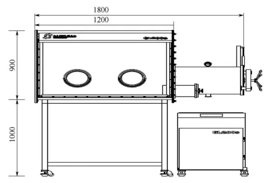
① Glovebox Type: Generally used only in laboratories or for small-scale production. It can be equipped with a built-in dehumidifier or connected to a dry gas source to control the moisture content inside. The single workstation glovebox is shown in the figure below.
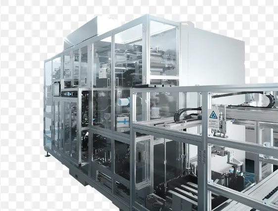
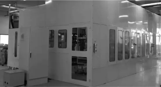
② Sheet Metal Casing with a certain sealing function. It is connected to a dry gas source and can be used inside a dry room or in a regular room with a transition room. The structure of the sheet metal casing is shown in the figure below.
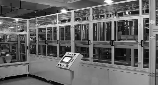
③ Aluminum Alloy Frame Casing. It is used inside a dry room and provides a certain barrier to moisture, ensuring safety for both equipment and personnel. The structure of the aluminum alloy frame casing is shown in the figure below.
2.2 Vacuum Pump
① Generally, screw pumps are commonly used.
② Placing the vacuum pump next to the Injection machine ensures high vacuum utilization efficiency and energy savings.
③ If the vacuum pump is placed far away, it would require pipelines to connect it. In this case, the loss of vacuum due to the pipelines should be considered. The longer and narrower the pipelines, the greater the loss of vacuum flow rate and vacuum level.
2.3 Injection Pump
① Nowadays, electric pumps are commonly used with ceramic pump heads, instead of the Hibar Injection pumps that were commonly used before 2010.
② Electric pumps are available in manual and intelligent variable types, with the latter often referred to as variable pumps.
③ The accuracy of electric pumps for electrolyte Injection is generally around 0.25%.
④ It is important to avoid pump clogging during actual production when using the Injection pump.
2.4 Electrolyte Transfer Tank
① The main purpose of the electrolyte transfer tank is to supply electrolyte (to the injection cup) at atmospheric pressure and maintain a constant level within a small range.
② The electrolyte in the transfer tank is pressurized to around 0.2MPa due to the presence of nitrogen gas as a protective gas, but the pressure decreases during usage.
③ When necessary, a two-layer or double-tank structure can be used for the electrolyte transfer tank. This allows for degassing of the upper tank to improve consistency and accuracy of the injected volume.
④ Filtration of the electrolyte can be performed if necessary.
⑤ When necessary, a differential pressure transmitter can be installed to monitor the filter.
2.5 Barcode Scanning System
① Barcode scanners are used to identify and read barcodes or QR codes.
② The scanned information is bound with the weight data and forms a database in the MES system.
2.6 Weighing System
① It includes components such as robotic arms, robotic grippers, and electronic scales.
② Electronic scales typically consist of separate weighing sensors and amplifiers to save space.
③ The corrosion resistance performance of the weighing sensors needs to be taken into consideration.
2.7 MES System
① The MES system mainly includes battery barcodes, pre-weighing, post-weighing, and checking the deviation of the injection quantity for qualification.
② The MES system enables the connection between the first and second injections, as well as the interconnection of the entire factory.
2.8 Leak Testing System
① Sometimes it is necessary to check the sealing of the sealing nozzle and the battery. Batteries with failed sealing are not subjected to injection.
② Vacuum or pressure holding methods are used for leak detection.
2.9 Liquid Supply System
① It includes the injection pump, valve, and pipeline.
② Some systems are equipped with temporary storage cups to improve efficiency.
③ Some systems use a movable injection needle method to inject liquid into multiple cups using fewer pumps.
2.10 Fixture/Pallet
① Used for battery positioning, fixtures or pallets are designed based on different battery structures and efficiency requirements.
② There are fixtures with fixed positions and pallets with movable configurations.
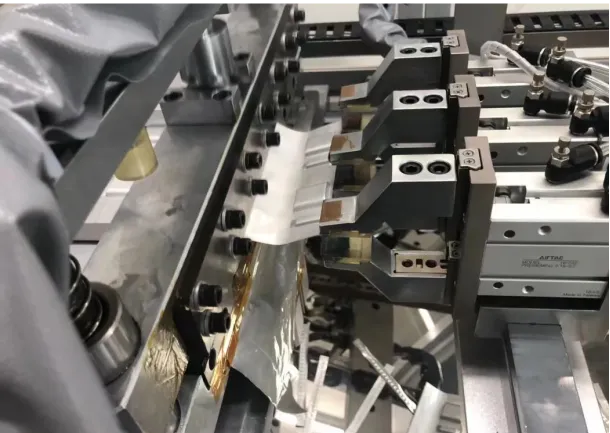
2.11 Settling Mechanism
① The settling mechanism includes injection cups, sealing nozzles, battery trays, compression mechanisms, pressure-vacuum valve and pipeline systems, etc.
② There are several types of settling methods:
·Flexible pouch batteries generally use a vacuum-atmospheric pressure cyclic settling method.
·Hardshell batteries generally use a vacuum-atmospheric pressure-positive pressure-atmospheric pressure cyclic settling method.
·Pressure settling can be classified into high-pressure settling and low-pressure settling. High-pressure settling refers to pressure exceeding 0.5MPa, while low-pressure settling refers to pressure below 0.3MPa. For prismatic batteries, especially those with explosion-proof membranes, an isobaric settling method is required when using high-pressure settling.
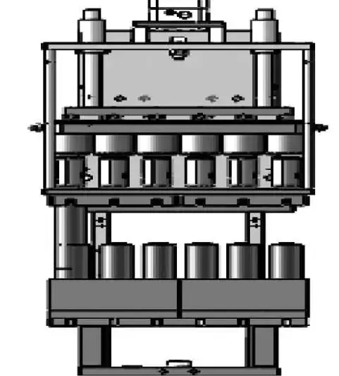
·The dome-shaped settling mechanism is shown in the figure. The settling unit of the tray loader is shown in the figure.
2.12 Material Conveyor Belt
The material conveyor belt is an automated connecting mechanism for the transportation of batteries into and out of the injection machine in the subsequent process.
03 Equipment Selection and Application Examples
3.1 Selection of Settling Methods
① Considering the current situation of mainstream injection machines, equipment selection mainly involves choosing different settling methods, including vacuum settling, low-pressure settling, and high-pressure settling.
② For pouch cell injection machines, the current practice is mostly based on the vacuum settling cyclic method. In the future, there might be a possibility of adopting high-pressure-isobaric settling method. On one hand, it can provide better impregnation effects, and on the other hand, it is speculated that it may save the subsequent dwell time.
③ Reference considerations for equipment selection for prismatic aluminum shell power batteries:
a. For injection settling time within 10 minutes: It is recommended to choose low-pressure settling (differential pressure method).
b. For injection settling time exceeding 10 minutes: It is recommended to choose high-pressure-isobaric settling.
c. For efficiency exceeding 20 PPM and settling time exceeding 10 minutes: It is strongly recommended to choose high-pressure settling.
④ For cylindrical steel shell batteries (18650, 21700, 26650, 32650, 32130, 46800):
a. For batteries with lower efficiency, such as 60 PPM for 18650 and 30 PPM for 32650, 46800, high-pressure injection with differential pressure method can be selected.
b. For batteries with higher efficiency, such as 120 PPM or 200 PPM for 18650, 60 PPM and above for 32650, as well as future 46800 series, it is strongly recommended to use high-pressure-isobaric injection.
c. For the 32130 series with steel shells, where the battery height is higher and electrolyte impregnation is more challenging, it is strongly recommended to use high-pressure-isobaric injection.
⑤ Cylindrical aluminum shell 32130 series batteries:
a. For batteries with lower efficiency or for secondary injection, the differential pressure method can be chosen.
b. For high-efficiency production lines, such as those with efficiency exceeding 30 PPM, it is strongly recommended to use high-pressure-isobaric injection, unless the injection for this battery is particularly easy and has a very short impregnation time.
3.2 Selection of Structural Modes
① The structure of injection machines generally includes rotary, linear, and zigzag (which is a type of linear) modes, each with some differences.
② The linear mode is further divided into parallel and series modes. In the parallel mode, all settling time is completed at the same settling station, while in the series mode, the tray battery goes through all settling stations to complete the entire settling time. The parallel mode has a higher time utilization efficiency compared to the series mode.
③ The rotary mode and parallel linear mode are essentially the same, while the zigzag mode is generally a series mode. The principles of the series linear mode and zigzag mode are basically the same.
④ Regardless of the mode, the key is the flow of batteries, the flow of battery trays, and the circulation of their use.
⑤ Large injection equipment may be a combination of rotary and linear modes.
⑥ For pouch cell injection machines, rotary or linear modes are generally used.
⑦ Dome-shaped high-pressure-isobaric injection machines are typically parallel linear injection machines.
04 Equipment Use and Maintenance
① Compared to other automated equipment, the biggest characteristic of a injection machine is that the electrolyte is corrosive, requiring special attention during use and maintenance.
② Nylon (PA66), Delrin (POM), PU tubing, and acrylic sheet (plexiglass) are not resistant to electrolyte corrosion and should be avoided for use.
③ The electrolyte is prone to crystallization. Before long-term shutdown, the injection pump, especially the ceramic pump head, needs to be disassembled for cleaning to prevent crystallization from clogging the pump.
④ Avoid having electrical circuits near the electrolyte, especially below it.
⑤ Guide rails and sliders should be protected from corrosion by the electrolyte.
⑥ If possible, do not cut off the supply of dry air during production shutdowns.