Lithium Battery Top 10 Key Equipment – Winding Machine
Sep 19, 2023


Follow me on:
Winding refers to a production process where electrode sheets, separators, and termination tapes with matching dimensions, which have been slit into strips, are rolled into jelly roll by controlling factors such as speed, tension, size, and deviation of the electrode sheets.

01. Overview of Winding Equipment Classification
Classification of Mainstream Winding Machines
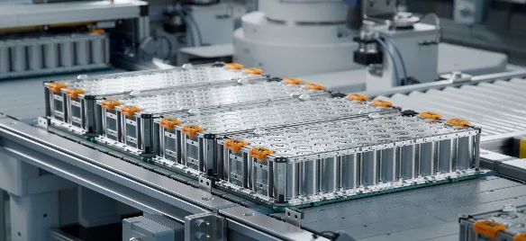
Lithium battery winding machines are used to wind lithium battery cells, and they are machines that assemble the positive electrode sheet, negative electrode sheet, and separator into a core pack through continuous rotation. The winding machine consists of positive and negative electrode feeding units, and the part where the positive and negative electrode separators are wound together is called the winding needle.
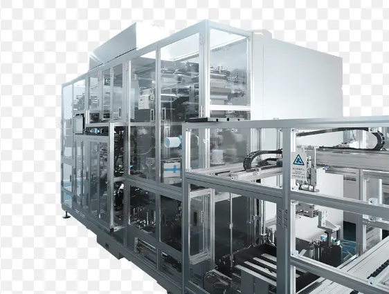
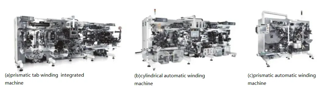
Based on the different shapes of the wound core packs, winding equipment can be mainly divided into two categories: prismatic winding and cylindrical winding. Prismatic winding can be further divided into prismatic automatic winding machines and prismatic tab winding machines. The battery cells produced through prismatic winding are primarily used for manufacturing power/energy storage prismatic batteries, digital batteries, and so on. Various types of battery winding equipment are shown in Figure.
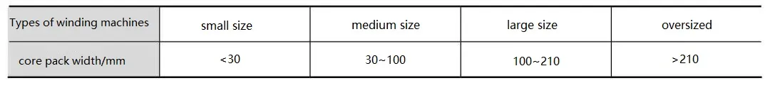
Winding machines can be classified into categories based on their level of automation, such as manual, semi-automatic, fully automatic, and integrated machines. They can also be categorized based on the size of the core packs they produce, including small, medium, large, and extra-large.
Table 1: Comparison Table of Winding Machine Specifications and Core Pack Sizes
The emergence of automated production equipment for lithium batteries began with the successful development of the first prismatic lithium battery winding machine by Kaido, a Japanese company, in 1990. In 1999, the Korean company Koem successfully developed lithium battery winding machines and assembly machines. Subsequently, the development of automated production equipment for lithium batteries began, with Japan and Korea remaining the leaders in this field, occupying the major market share due to their excellent technology and reputation. Domestic winding manufacturing equipment in China started in 2006, initially with semi-automatic circular and prismatic winding machines, followed by automated tab-making and winding integrated machines.
1.2 Challenges in the Development of Winding Processes
It is undeniable that the winding process has significant advantages in terms of production equipment, technological processes, efficiency, and cost, based on years of technological accumulation. However, with the increasing demand for standardization, high capacity, and large-sized automotive-grade power batteries, the winding process is facing challenges and limitations.
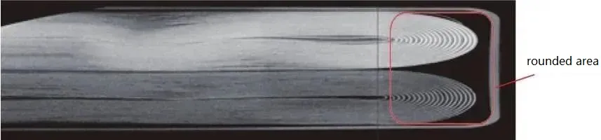
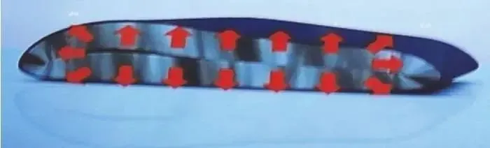
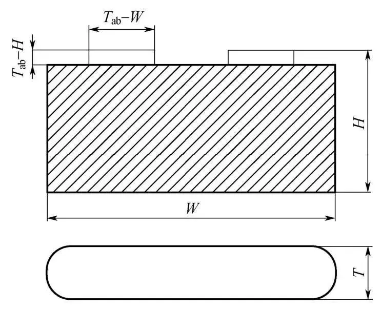
The text describes the standard structural characteristics of a wound cell, with rounded corner regions at both ends. During the charging and discharging processes of the battery, inconsistent expansion and contraction can lead to an increase in the gap between the electrode plates and the separator. When the electrolyte is not sufficient in this area, it can impact the capacity performance, and long-term use can pose safety issues related to lithium plating. Moreover, with the increasing demand for higher energy density, silicon-based anode materials are gradually being introduced. However, due to the significant expansion of silicon-based anodes, there is a risk of inner electrode plate breakage in the wound electrode assembly, which affects the battery’s lifespan and limits the amount of silicon material that can be added.
1.3 Future Development Direction of Winding Machine
① High speed and high precision: The linear speed of winding electrode pieces will increase from the current 2-3m/s to 5m/s, and the alignment precision of the winding electrode pieces will be improved from the current ±0.3mm to ±(0.1-0.2)mm.
② High qualification rate: CPK will increase from 1.33 to 1.67, and eventually reach above 2.0, achieving a level of zero-defect.
③ Stability: Increase the average time between failures, from the current tens or hundreds of hours to thousands or tens of thousands of hours.
④ Digital and intelligent control of equipment: Online monitoring of winding tension, alignment of electrode pieces and separators, closed-loop optimization of winding parameters and final battery performance parameters, leading to an improvement in winding qualification rate.
⑤ Integration of laser cutting and winding: Integration of laser cutting and winding processes to achieve equipment integration.
⑥ High-speed winding machine: Breakthroughs in continuous and uniform motion technology of the separator will result in a doubling of winding efficiency.
02. Equipment Principle, Composition, and Key Structures
2.1 Winding Machine Principle
The winding machine is mainly used for the automatic winding of prismatic or cylindrical bare battery cells. The equipment adopts a structure with two or more winding needles and single-side needle extraction. The positive and negative electrode electrode pieces and separators are actively unwound, and the electrode piece-separator roll exchange, automatic alignment correction, and automatic tension detection and control are performed. The electrode pieces are introduced into the winding section by the clamping roller drive mechanism and are automatically wound together with the separator according to the process requirements. After winding is completed, it automatically switches to the next station, cuts the separator, and applies the terminal tape. The finished bare battery cell is automatically unloaded, undergoes pre-pressing and scanning, and the qualified products are automatically transferred to a tray and then to the subsequent processes. The defective bare battery cells are automatically unloaded to the collection area for defective bare battery cells.
2.2 Explanation of Winding Machine Mechanism
① Pre-winding: This is the initial feeding process of the positive and negative electrode electrode pieces. During this process, the positive and negative electrode electrode pieces are fed by a motor at a constant speed. The rotation speed of the winding needles needs to be synchronized with the feeding speed of the electrode pieces. This process involves six motors. There are two types of synchronization involved: synchronization between the unwinding speed of the separator and the speed of the winding needles, and synchronization between the feeding speed of the electrode pieces and the speed of the winding needles.
② Winding process: After the initial feeding process of the positive and negative electrode electrode pieces is completed, the separator tightly wraps around the electrode pieces and begins the winding process by winding around the winding needles for one revolution. During this process, the feeding speed of the electrode pieces is adjusted by detecting the tension of the material roll. This adjustment ensures a constant tension of the material roll during the winding process.
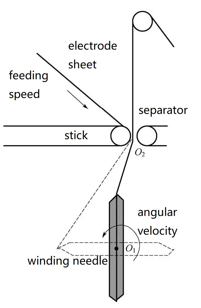
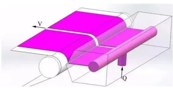
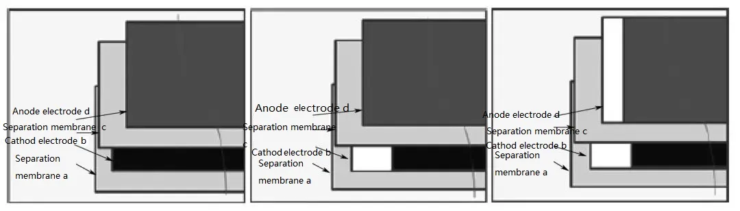
Schematic Diagram of the Winding Process
The schematic diagram of the winding process is shown in Figure. This process involves six motors. There are two types of synchronization: synchronization between the unwinding speed of the separator and the speed of the winding needle, and synchronization between the feeding speed of the electrode piece and the speed of the winding needle. The control issues in the pre-winding stage belong to open-loop control problems, as there is no feedback calibration for true synchronization between the two. This requires us to establish an accurate winding speed model. Tension measurement of the material roll is present during winding, allowing for the use of closed-loop feedback control techniques in the control process.
In the winding process, we actually control the rotation frequency of each motor, while the actual speed is a function of the radius of the material roll and the winding needle, which dynamically changes over time. Currently, in the absence of actual sensors for measurement, we assume that the change in the intermediate radius of the material roll after one loading process follows the Archimedean spiral law, without considering the impact of manual roll exchange. Additionally, the initial radius of the winding material is predetermined in the program.
③ Dynamic Modeling of the Winding Process: Since the pre-winding process belongs to open-loop control, an accurate mathematical model is crucial in determining the success or failure of the system.
2.3 Equipment Composition and Key Structures
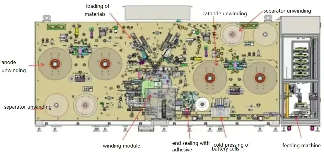
The main modules of the equipment include:Electrode/separator automatic unwinding module, Electrode/separator roll exchange module, Automatic alignment correction module, Guide roller module, Electrode tab guiding and flattening module, Main drive module, Tension control module, Tension measurement/display and storage module, Electrode feeding module, Separator electrostatic removal device, Electrode tab folding/bending and electrode damage detection module, CCD online inspection module, Electrode cutting module, Dust removal system, Rejection module for defective electrode and separator rolls, Winding head assembly, Separator cutting module, Separator adsorption module, Terminal tape application module, Automatic unloading module, Bare cell pre-pressing module, Discharging module, Equipment frame and main panel module.
The key structures are as follows:
1. Electrode/separator automatic unwinding system: It consists of the electrode/separator automatic unwinding shaft, belt feeding components, and unwinding alignment correction. It achieves functions such as fixation, automatic unwinding, and automatic exchange of electrode/separator rolls. The unwinding shaft adopts mechanical or pneumatic expansion methods, and auxiliary blocks and edge detection mechanisms facilitate quick positioning.
2. Automatic edge correction module: It consists of multiple-level correction mechanisms, which can employ various methods such as hanging shaft movement, guide roller swinging, and nip roller driving for edge correction. By real-time detection, control, and display of the material’s edge during belt movement, it accomplishes real-time correction of the material’s edge. The positioning of sensors is designed to avoid dust accumulation that could affect the accuracy of edge value detection. The main parameters include unwinding alignment accuracy of ±0.2mm and in-process alignment accuracy of ±0.1mm.
3. Tension control system: It consists of tension detection sensors, tension control mechanisms, and a display/storage module. The tension control mechanisms can include linear motors, low-friction cylinders, or servo motors. The tension detection mechanism is positioned as close as possible to the winding needle mechanism. By effectively controlling the tension of the material during belt movement, it enables the setting and adjustment of tension for each winding cycle. To achieve precise control, it is important to prevent deformation of the bare electrode due to winding tension issues. As the winding diameter gradually increases during the winding process, the tension needs to be increased to ensure the tightness of the electrode. Within each winding cycle, it is necessary to control the fluctuation of tension within a certain range.
4. Electrode Feeding Module: It consists of the positive and negative electrode nip roller driving mechanism and the feeding mechanism, responsible for the feeding of electrodes before the winding process. During the winding process, the feeding position and relative position of the material remain unchanged. It is desirable for the feeding nip rollers and the free length of the electrode before being fed to be as short as possible, while ensuring proper feeding and tailing. The electrode feeding area has the functionality of air blowing and guiding, with digital pressure monitoring. The direction of air blowing and guiding is adjustable and equipped with an angle scale. Additionally, the electrode feeding is efficient, low-noise, free from pollution, and allows for easy quantifiable adjustment of the tilt angle.
5. Electrode Cutting Module: It consists of the positive and negative electrode pressing and cutting mechanisms, capable of automatically detecting the mark hole at the end of the electrode (produced by laser die-cutting). Once the set number of electrode tabs is reached or by recognizing the spacing between tabs, the module can cut the electrode at a predetermined length. It also allows for the functionality of cutting electrodes at specific lengths. The cutting blade is recommended to be made of hard materials such as tungsten steel, and both the moving blade and fixed blade have specific angles. Additionally, the cutting area should have isolation protective shields and warning signs, while also being treated to prevent adhesion.
6. Module for Defective Electrode and Separator Removal in Single Coils: It consists of a servo motor, coupling, and linear guide mechanism, and is programmed to perform independent removal functions. It enables the separate removal of defective positive and negative electrode coils without separators. When a defect is detected in the positive or negative electrode, it can automatically remove the coil together with the separator or independently remove them separately. Defective products are discharged into a separate mechanism and collected in a reject box. During the process of removing a coil without separators, the electrode does not interfere or rub against other components, ensuring it does not affect the alignment of the next material.
7.Winding Module: It consists of a dual-station or multi-station mechanism equipped with dual servo motors or multiple servo motors to drive the winding mechanisms. Each set corresponds to 2 or more winding needle mechanisms. It is also equipped with a locking and positioning mechanism for tower rotation after station change. This module enables the winding of battery cells and automatic switching between different winding stations, while maintaining a constant line speed during winding. It can achieve functions such as winding the positive or negative electrode first, as well as simultaneous feeding and winding of both electrodes.
Preventing the generation of internal folds within the battery cell during the winding process is crucial. Internal folds can lead to local lithium plating during the actual use of the battery, posing significant safety risks.
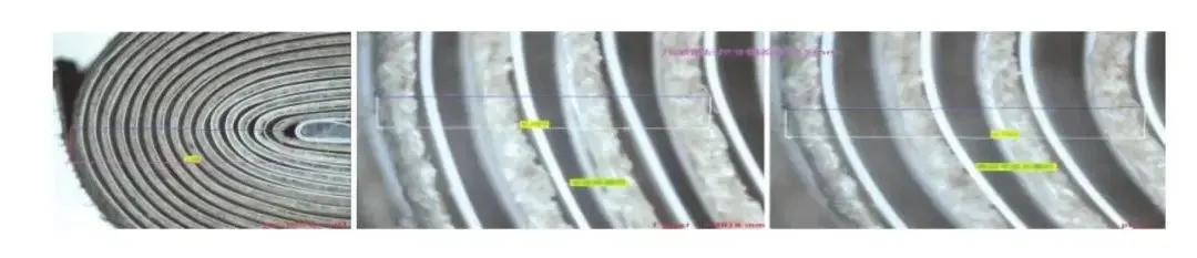
There exists a law of winding wrinkles regarding the generation of wrinkles: For different types of winding needles, there is a possibility of wrinkles between the layers of the wound core. The reason for wrinkles is that as the electrode accumulates in each winding turn, the interlayer radius of the electrode increases by δ, and the accumulated length of the electrode also increases. When the rate of increase in the accumulated circumference length of the electrode is not equal to the rate of increase in the winding radius, wrinkles occur in the internal electrode after the winding needle compresses the core. This is known as the law of winding wrinkles.
Generally, diamond-shaped winding needles, due to their structural characteristics, experience significant tension fluctuations of the electrode during the winding process. The growth rate of the electrode circumference is inconsistent with the growth rate of the radius, which can lead to the occurrence of interlayer wrinkles. In comparison, elliptical, oval-shaped, and circular winding needles do not have the issue of wrinkles.
8.The membrane cutting module consists of a hot cutting knife mechanism and a protective mechanism, and it can cut the membrane according to the required length for the product. The cutting part needs to have high temperature and blade safety protection, along with warning signs, and should be equipped with a heat insulation device. It has functions such as blowing air and using a rotating tower spindle to flatten the cut membrane, preventing wrinkles in the membrane. After the membrane is cut, it needs to be immediately sucked to prevent the membrane from curling due to static electricity, which could result in poor finishing of the membrane.
9.The termination tape pasting module consists of an automatic tape preparation mechanism, a tape mark hole sensor, and a tape application roller. After the tape roll is unwound, it is automatically prepared to the required length. The module also automatically detects the tape mark hole and applies it to the corner or end of the bare electrode core. The termination tape pasting mechanism is designed to be adaptable, allowing the tape placement to be adjusted based on the position of the bare electrode core on the winding needle. The tape unwinding mechanism has active unwinding capability and includes an anti-static function.
10.The pre-press and cutting module consists of a bare electrode core unloading mechanism, a bare electrode core pre-pressing unit, and a bare electrode core transfer mechanism. It automatically unloads the bare electrode core from the winding needle and applies pre-pressing during the transportation process of the good-quality bare electrode core. After pre-pressing, the QR code on the surface of the electrode core is scanned to bind the information, and then the electrode core is transferred to the cutting machine via a transfer belt. The pressure plate in contact with the bare electrode core is treated to prevent sticking, and it is equipped with a pre-pressing pressure sensor to prevent damage to the bare electrode core.
11.Dust removal system: It consists of a dust removal device at the positive gravity sheet cutter, a brush device, static electricity removal components, a positive gravity sheet/local magnetic rod, a separate dust removal cover, and an FFU system. and the bare cell surface and prevent the environment from entering the bare cell. Moreover, the inlet/outlet duct of the dust collector is made of reinforced and anti-static materials. The inner wall of the tube is smooth. The filter element is made of anti-static material. The air inlet duct should avoid right-angle turns. The integral closed cover uses an isolated transparent cover and partitions to isolate different areas, namely the facing electrode area, contact area, winding area, and unloading area, to prevent inter-warehouse mixing and external mixing. At the same time, by using an FFU system to control the airflow inside the equipment, it is maintained at a slightly higher positive pressure than the external environment. All rotating connectors, fasteners, covers, and straps in areas prone to friction and collisions should use a combination of metal and non-metal or entirely non-metal materials. Components such as pneumatic elements should be made of materials that are free of copper and zinc, and they should undergo surface treatment to prevent the generation and contamination of copper and zinc dust.
The negative pressure suction pipelines converge into a main suction duct and are then led out of the equipment. The entire airflow field is simulated through computational modeling. The inlet duct requires a certain air velocity while avoiding sharp bends. If the bend angle exceeds 45 degrees, an access point for maintenance is needed.
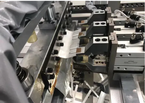
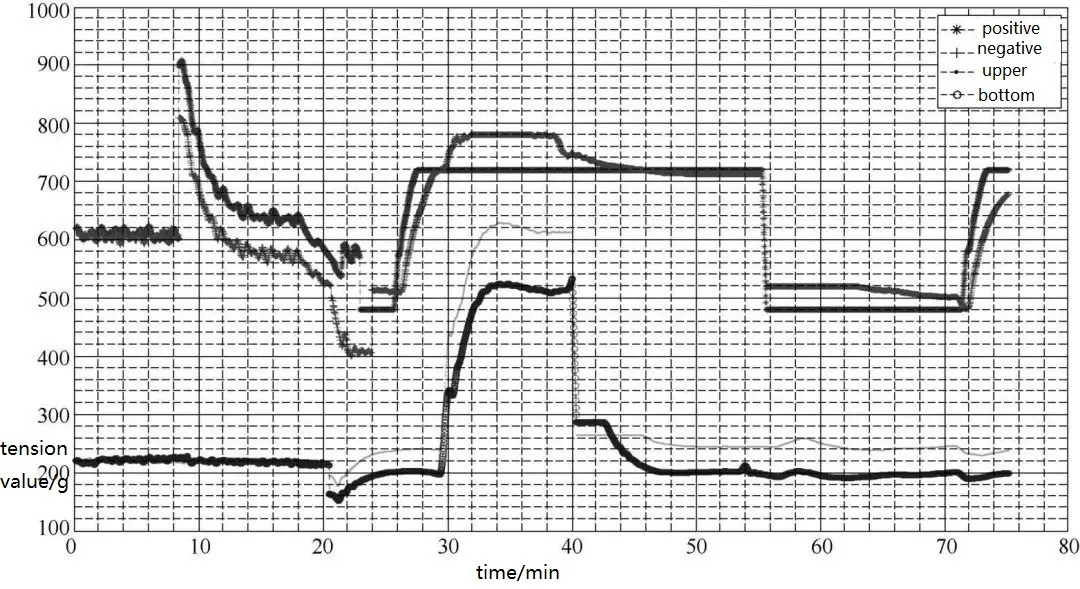
12.The electrode process detection system consists of multiple sets of high-resolution industrial cameras, machine vision lighting sources, mounting structures, industrial computers, and displays. The vision CCD cameras capture images of the positions of the cathode electrode, anode electrode, upper and lower diaphragms, and specified markers at the four corners of the battery cell. The machine vision software on the PC analyzes the two-dimensional distances between the material edges or boundaries and the marker positions. Real-time calculations are performed by the computer to determine the displacement values between the same circle of anode and upper diaphragm, same circle of cathode and anode, same circle of cathode AT9 and anode, same circle of lower diaphragm and cathode, and the previous circle of cathode and the next circle of anode. These values are displayed in real-time as scatter plot curves and layers on a monitor or touch screen. Additionally, the system monitors the displacement values of the battery cells.
The system processes the data and calculates the maximum, minimum, and average displacement values between each layer of bare electrode cores. The detection range covers the first circle to the last circle of the battery cell, ensuring a comprehensive inspection.
The CCD detection schematic is shown in Figure. The detection system is installed near the outer side of the winding needle of the winding machine, ensuring that it does not interfere with the movement and operation of the winding components. The angle and distance from the large plate are continuously adjustable. The structural components need to have high strength and firm installation to avoid affecting the measurement accuracy. Both the camera and lens are designed with collision protection to prevent any accidental collisions that could cause displacement or damage to the structural components.
03.Device Selection and Application Cases
(1) Clarify Incoming Process
Confirm the compatibility requirements of incoming materials, including parameters such as the width and thickness range of the positive and negative electrode sheets, wavy edges, serpentine bends, coil diameter, and inner diameter of the reel.
(2) Clarify Product Specifications
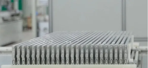
① Confirm the compatibility of bare cell specifications, including main parameters such as cell thickness, width, height, etc.
Example of Cell Specifications
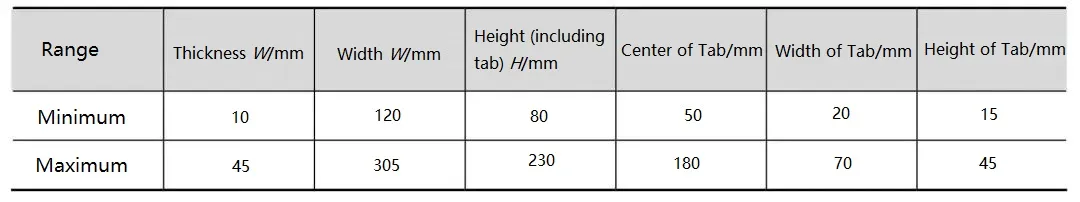
Cell dimensions as shown in the diagram
Clarify Adhesive Application Process, whether using single-sided or double-sided adhesive. Specify dimensions such as tape width and adhesive length.
(3)Clarify Equipment Configuration
① Functional Configuration: Based on the incoming process and product specifications, confirm the overall equipment configuration requirements. Unwinding configuration includes dual unwinding for positive and negative electrodes with automatic reel change function, double shaft unwinding for separation membrane, and manual reel change. Misalignment control includes three or more levels of misalignment correction during the electrode process. The winding head adopts direct drive, and the types of winding needles include diamond-shaped, elliptical, or circular needles, with a choice of dual or triple needle configuration. The needle feeding employs a dual gripper mechanism for feeding. After cell feeding, pre-pressing is performed before the subsequent feeding process.
② Establish and enforce general specifications for mechanical, electrical, and information systems.