Lithium Battery Top 10 Key Equipment— Pouch Package Equipment
Oct 11, 2023


Follow me on:
The pouch pack battery assembly line is a crucial part of the mid-to-late stage processes in lithium battery manufacturing. It is primarily responsible for handling the assembled or wound bare cells and performing operations such as tab welding, taping, cell casing, and top-side sealing. The design principle of the assembly line is based on the production process of lithium batteries, taking into account factors such as cell size, structure, and desired production efficiency.
1.Overview of pouch Pack Assembly Line
1.1 Design Principles and Principles of the Assembly Line
The selection of the form of the assembly line for pouch pack batteries is primarily determined by the size specifications of the cells. For cells with a length below 390mm, the tab welding machine, packaging machine, and the subsequent section of the packaging machine generally adopt a turntable structure driven by a cam splitter. This structural layout is compact and occupies a small floor area. However, it is limited by the precision of the turntable. The larger the turntable, the poorer the assembly accuracy for the cells. Additionally, the increased load also affects the difficulty and efficiency of starting and stopping the turntable.
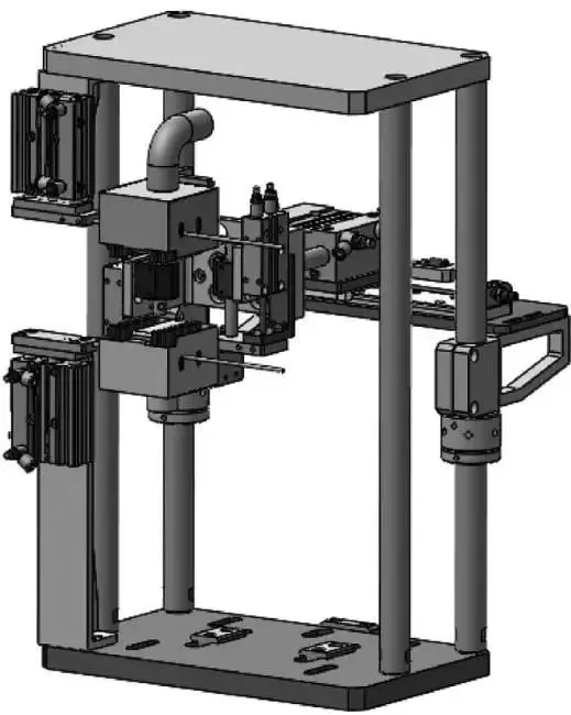
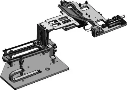
For cell specifications with a length above 390mm, the tab welding machine, packaging machine, and the subsequent section of the packaging machine generally adopt a linear structure. This layout allows for precise positioning during station switching for large batteries and offers high efficiency in station switching, providing better potential for improving production efficiency. However, this layout has the drawback of occupying a relatively narrow floor area, and the drive mechanism for station switching is more complex, resulting in relatively higher costs. The layout of a linear assembly line is shown in the diagram below.
1.2 Assembly line efficiency distribution
In the design process of the construction line, the control of the rhythm mainly depends on the limitations of the bottleneck station of each station production. For example, the actual production capacity requirement is 8PPM. Regarding the comprehensive production capacity of the equipment, the actual design is generally based on 10PPM, and the limit work limit is The positions will be carried out in a multi-station manner, such as the protective sheet feeding mechanism in the tab pre-welding of the welding machine section, the Tab feeding mechanism in Tab welding, the top and bottom sealing packaging time, side sealing packaging time in the packaging machine, etc. . After comparing the production capacity requirements, calculate the process time required for each station. If it is not met, multi-station design is required. For example, when the equipment efficiency requirement is 12PPM, the process time and production time of each battery cell is 5 seconds. Some customers’ packaging time requirements reach 4 to 5 seconds, plus the switching time of the battery cell station and the action time of the packaging mechanism. , cannot meet the production efficiency requirements, so it is necessary to design a double workstation of this station to meet the production efficiency requirements. The beat distribution of other workstations is the same.
1.3 Logistics methods
When batteries are assembled, logistics must be used to transfer and switch between workstations. Therefore, reasonable logistics methods need to be selected for batteries in different states.
① For the bare cells discharged from the stacking machine, in order to ensure the transportation efficiency of the cells and protect the safety of the cells, the method of double-speed chain + cell clamp is usually used. The double-speed chain has high transportation efficiency and is suitable for long-term production. It has the advantages of long-distance transportation, large load, simple maintenance, etc., and the double-speed chain profile has great flexibility for setting stops and other auxiliary structure installation and adjustment. The disadvantage is that the double-speed chain is prone to friction and generates dust. In order to avoid the impact of dust on the battery cores, some manufacturers use magnetic levitation conveyor lines to transport bare batteries, but this is expensive.
②The electric cores are transported from the stacking machine to the welding machine. Each station on the welding machine has high requirements for the positioning accuracy of the electric cores. The electric cores are loaded into the welding fixture and adopt a step-by-step transportation method. In order to ensure accuracy According to the requirements, the drive adopts the circulation structure of servo motor + shift fork.
③After the battery cores are unloaded from the welding machine, the servo motor + synchronous belt transportation method is generally used. This can ensure the equal spacing of the battery core transportation and facilitate the accuracy of the robot’s unloading and loading grabbing positions. Similarly, , the same method is adopted after the packaging machine, which is economical and efficient.
1.4 Cell positioning methods and principles
On the battery cell assembly line, the battery manufacturer has certain dimensional accuracy requirements for the battery cells in terms of process. Therefore, the battery cells need to be positioned before the battery enters the assembly line. The battery cells are positioned on the same basis. Each subsequent work station The adjustment is also based on this to ensure the consistency of battery assembly.
The shape of the battery core body is rectangular, so in terms of positioning, two sides are usually used as the positioning reference, and the other two sides are used to position the battery core by pushing. You can also use the central positioning method of the battery body to push the battery body forward, backward, left and right at the same time. The choice of positioning method generally depends on the process size requirements of the battery core and the convenience of structural design, as long as the benchmark is consistent.
1.5 Dust control
In the battery production process, the most fatal hazard is that metal dust enters the battery body, causing a series of problems, such as battery short circuit and fire. In order to avoid this situation from happening, it is necessary to strictly control the sources of dust in the assembly line and remove them as much as possible. To control dust, we must first find out the source of dust, and then take targeted measures.
①Lamination machine conveyor line (double speed chain). During the transportation process, the double-speed chain will rub against the double-speed chain profile to generate a lot of dust. For this kind of dust, it is necessary to install a dust-proof plate on the double-speed chain line body to prevent dust from falling onto the battery core. At the same time, the battery core clamp should be as small as possible. The conveyor is transported by upper and lower clamping, and the empty fixtures on the return line are dusted at fixed points. The dust removal method is carried out by blowing + suction. Since the line is relatively long, the frequency of manual cleaning needs to be increased to prevent dust accumulation, etc. .
②Assembly line. When batteries are circulated in the assembly line, some workstations themselves can generate dust, such as the pre-soldering, cutting, tab welding, and solder stamping stations of the tabs. As long as there is a cutting or welding station, they will be installed. A special dust removal mechanism performs uninterrupted dust collection. The picture below shows the dust removal station map.
1.6 Quality Control
In order to ensure the stability and consistency of battery production quality, there will be corresponding detection sensors for quality control in all aspects of battery production. For the assembly line, the specific manifestations are as follows:
① The color sensor is used to detect the polarity of the incoming battery core, mainly to prevent the battery from being discharged reversely after manual intervention.
② Scan the battery code to ensure that the battery information is uploaded to the MES system in a timely manner, which facilitates the tracking of battery production information.
③X-ray inspection of the battery core is used to detect the alignment of the battery core to prevent the subsequent production of severely misaligned batteries.
④Tab polarity detection and positive and negative detection to avoid welding errors.
⑤ Glue detection after Tab welding to avoid direct contact of the solder print with the aluminum-plastic film during subsequent packaging.
⑥ CCD size inspection after Tab welding to ensure the size consistency of battery core production.
⑦After welding, the Hi-pot test is conducted on the battery cell to ensure there is no conductivity between the positive and negative terminals of the welded cell.
⑧ Aluminum plastic film deviation control to ensure the punching yield rate of aluminum plastic film.
⑨ CCD size detection of the battery after packaging to ensure the consistency of the appearance and size of the battery.
⑩ After encapsulation, the Hi-pot test is conducted on the battery to ensure there is no conductivity between the positive and negative terminals of the encapsulated cell.
⑪The insulation test of the battery after encapsulation is conducted to ensure there is no conductivity between the positive and negative terminals of the encapsulated cell and the aluminum-plastic film.
⑫ Test the seal thickness of the battery after packaging to ensure the consistency of the battery seal after packaging.
Through the above-mentioned series of control methods and points, the quality of the battery on the entire assembly line can be effectively controlled.
2. Main functions and description of equipment
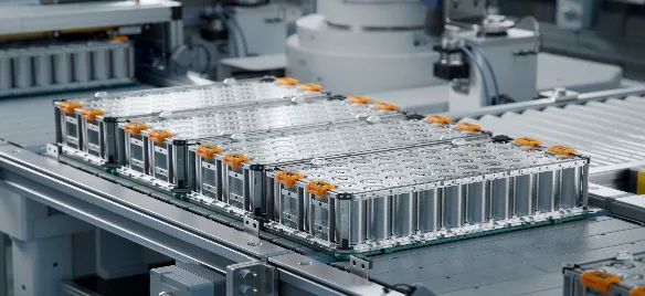
Lithium batteries are a type of battery that uses lithium metal or lithium alloy as the negative electrode material and uses a non-aqueous electrolyte solution. The main components of lithium batteries are positive and negative electrodes, electrolytes, separators and casings. pouch-pack lithium batteries are batteries with a polymer shell placed on a liquid lithium-ion battery and packaged with aluminum-plastic composite film. Compared with cylindrical batteries and aluminum-shell batteries, the composition of the battery is the same, but the packaging form and the physical structure of the battery are different, which leads to the assembly form and production process of the pouch-pack battery being different. pouch-pack batteries The structure is shown in the figure.
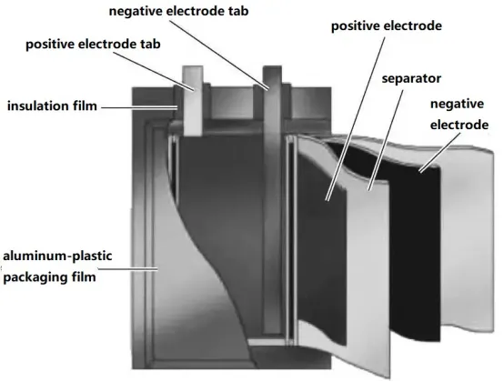
pouch cell structure
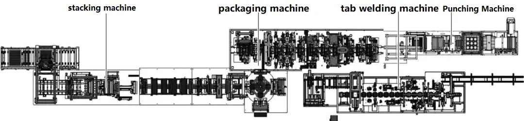
The production process of the pouch pack battery assembly line can be divided into three parts: the first part is the tab welding part, the second part is the packaging machine part, and the third part is the pit punching machine part
The main technical indicators of a pouch cell assembly line are as follows:
① Product qualification rate: ≥99%.
② Overall production efficiency of the line: Depending on the requirements of the production line.
③ Number of operators required for the production line: 2 persons.
④ Overall equipment utilization rate: ≥98% [Calculation formula: (24h – downtime – alarm time)/24 × 100%].
⑤ Packaging equipment qualification rate: ≥98.8%.
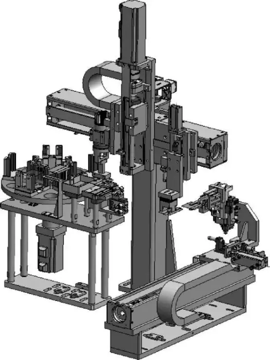
3.Equipment Composition and Key Structures
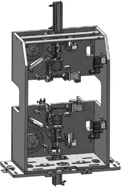
The pouch cell assembly line mainly consists of an electrode tab welding machine, a packaging machine, and the post-packaging machine.
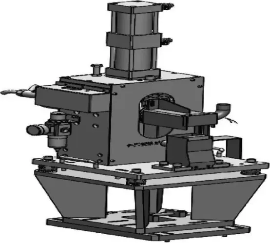
3.1 Tab Welding Machine
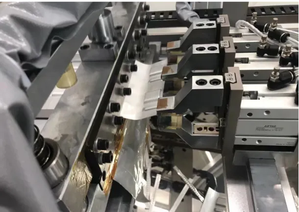
The tab welding machine is responsible for folding and pre-welding the copper or aluminum tabs of the bare cells received from the stacking machine. It performs processes such as final ultrasonic welding of the tabs, flattening the weld imprints, dust removal, and adhesive application to prepare for the subsequent encapsulation in the aluminum-plastic film pockets. The key structures of the electrode tab welding machine include pre-welding of the cell tabs, tab cutting, final welding of the cell tabs, weld imprint flattening and dust removal, and adhesive application.
The tab welding machine performs pre-welding and final welding of the tabs of the bare cells received from the stacking machine. Its key structures include tab cutting, tab pre-welding, tab-to-tab welding, and weld imprint dust removal.
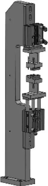
Tab pre-welding involves folding and welding the copper or aluminum tabs of the cell, preparing them for the final welding process. The components of this structure include a pre-welding machine, a welding machine base, a folding mechanism, and a dust removal mechanism. The structure of tab pre-welding is shown in the diagram.
1) Pre-soldering of tabs
The function and action of this structure are used to realize ultrasonic pre-welding of the tabs. The welding head under the welding machine is fixed (the design of the welding head, welding base, and base needs to be communicated with the customer). After the cell tabs are in place, the cylinder is pressed down The pallet clamp reaches the pre-welding working height, and dust is collected while welding; and the tabs are gathered together during welding. There is a protective device on the welded battery core to prevent welding slag from falling into the battery core. The lower welding head has a dust cover, and there is a dust adsorption device inside the dust cover, including a blower device and a dust adsorption device to ensure that the welding dust can be absorbed cleanly; the dust suction wind speed is required to be ≥15m/s.
For the welding position accuracy of the tab pre-soldering, the deviation in the up and down direction is required to be ≤±0.2mm, and the deviation in the left and right direction is ≤±0.2mm.
Remarks: The welding packaging line needs to be connected to the data according to the welding machine, and can collect key welding parameters (welding parameters include energy, power, time, pressure, etc.), and can receive relevant welding abnormal information, perform abnormal alarms and discharge cell NG.
2)Tab cutting
The tab cutting structure is mainly used to cut the pre-welded copper and aluminum tabs neatly. It consists of upper and lower cutting blades, upper and lower cutting blade guiding mechanisms, dust removal mechanism, waste material guide chute, upper cylinder, lower cylinder, and other components. The structure of electrode tab cutting is shown in Figure.
This structure is used to achieve automatic cutting of the positive electrode tabs after pre-welding. The cutting tools use SKD11 with diamond-like carbon coating to prevent adhesion. Backup tools are used in a one-to-one approach, and tungsten carbide treatment can be applied to SKD11 as per customer requirements. There is a digital micrometer for adjusting the cutting position, making it convenient for manual adjustment, and the cutting blade cuts onto the pre-welding weld imprint. The adjustable range of the cut tab length is 0-10mm, with a cutting accuracy of ±0.1mm. The cutting blade’s lifespan requirement is that it can be used for a minimum of 300,000 times (with a reminder for sharpening every 200,000 times), and it can be resharpened more than 10 times. There is a dustproof hood at the cutting blade, isolating the cutting mechanism from the external environment. The dustproof hood has a dust adsorption device to ensure cleanliness by adsorbing cutting waste and dust. The dust extraction airflow velocity requirement is ≥15m/s. There is a receiving box within the cutting mechanism to collect the cut foil material. The cutting plate has a convex design, and the spring force is adjustable. Before cutting, the protective film on both sides is pressed to prevent the protective film from warping and affecting subsequent processes.
3.Tab Final Welding
The tab final welding process consists of the positive/negative tab feeding mechanism and the main welding process of the positive/negative electrode tabs.
① Positive/Negative Tab Feeding Mechanism: The positive/negative tab feeding mechanism consists of a tab magazine-style feeding mechanism, servo lifting device, tab suction mechanism, secondary positioning mechanism, magazine mechanism detection sensor, etc. It is used to achieve automatic feeding of positive and negative tabs.
The main function of the positive/negative tab feeding mechanism is the critical process of welding the tab conductive handle and the pre-cut positive/negative tabs together. In actual production, the tabs need to be continuously fed. To ensure uninterrupted material change without stopping the machine, a tab buffer mechanism needs to be designed in the mechanism. The tab retrieval robot needs to have a rotation function to prevent mistakes in the orientation of the tabs. The polarity detection of the tabs is to detect the polarity of the positive and negative tabs to prevent incorrect placement by humans. The positioning mechanism for the tabs is required due to the positional accuracy between the cell tabs and the tabs during welding. The positioning reference points can be the sides of the tabs and the PP adhesive or the surroundings of the tabs, depending on customer requirements. The feeding mechanism for the tabs securely holds the properly positioned tabs and delivers them to the predetermined position for final welding. Due to the positional accuracy requirements, the driving mechanism is a combination of a servo motor and a ball screw to ensure precision. The positive/negative tab feeding mechanism is shown in the accompanying figure.
The functions and actions of the positive/negative tab loading mechanism are as follows:
a. There are a total of 5 magazines on the magazine mechanism. The positive and negative magazines are distinguished by colors and markings. One magazine can hold 200 tabs at a time, and it can work continuously for more than 2 hours with one feeding.
b.Tab’s dimensional accuracy for incoming materials: Tabs are manually placed into the clip during material reception. The battery utilizes brushing, air blowing, and electrical shaking procedures to prevent multiple pieces, ensuring a 100% qualification rate. The detection of the conductive handle’s position is used to identify the positive and negative sides. The positive and negative terminal clamps are distinguished by color. The transfer of 6 magazines is completed by servos, and there are sensors on the material loading position to detect the presence of materials. Servo rotation is adopted to avoid excessive positioning offset, which may cause distortion of the tab ears.
c. Tab positioning uses mechanical positioning to position the short side of the conductive clip and the tab glue.
d. For clamping and loading, a finger cylinder is used to clamp the conductive handle in the largest area to avoid sliding of the conductive handle. The servo transfer method achieves accurate feeding, and the tab positioning accuracy is ±0.2mm.
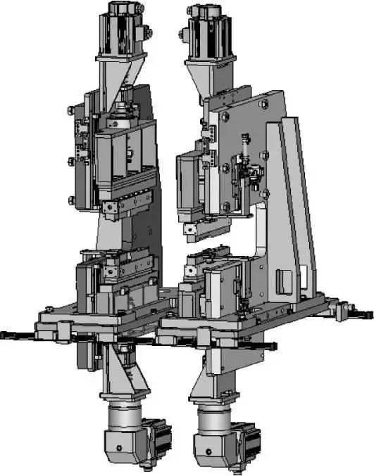
②Main welding of positive/negative electrode tabs. The main components of the main welding of positive/negative tabs are ultrasonic welding machine, positioning mechanism, detection system, dust collection system, etc. The main welding of positive/negative tabs is as shown in the figure.
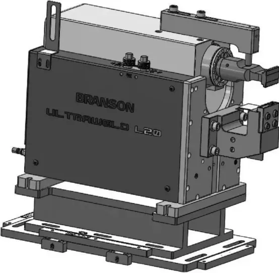
The main welding of positive/negative tabs is used to achieve ultrasonic welding of positive and negative tabs. The lower welding head of this mechanism is fixed, and the tabs are welded above the battery tabs. The entire welding machine can be adjusted horizontally to adapt to process requirements.
The technical features of positive/negative tab main welding are as follows:
a.The single-use lifespan of the welding tip/bottom die is ≥50,000 times, and it can be regrinded for more than 5 times on a single surface. The compatibility of the welding tip/bottom die with the number of layers of tab welding is ≤50 layers. The design of the welding tip/bottom die and the base needs to be communicated with Party A.
b.After welding, there is a device to detect whether the tab is welded to the conductive handle. The system will generate an alarm and trigger the NG (non-good) device if there is any issue with the battery.
c. The key parameters of welding (welding parameters include energy, power, time, pressure, etc.) can be set with upper and lower limits. It has the functions of online detection, abnormal alarm, cell NG exclusion, and reserved conductive handle for up and down welding.
d. Dust collection treatment: There is a protective device on the side of the welded battery core to prevent welding slag from falling into the battery core. Make a dust cover to follow the movement of the welding head, and turn on the dust during ultrasonic welding. The dust suction wind speed is 20m/s, which can effectively suck away metal dust.
e. Accuracy: The tab positioning accuracy is ±0.2mm; the welding position accuracy is ±0.2mm up and down, and ±0.2mm left and right.
f. The welding parameters have local storage and have the interface function to connect with MES. A manual dust removal port is added, and the welding station has the function of checking whether the welding tab is present and detecting the tab after welding.
4) Dust removal from tab soldering
The dust removal of the tab welding marks is crucial to the yield rate and safety performance of the battery core. The main reason is that the ultrasonic welding process is mechanical friction welding, which will produce a lot of metal dust, and many sharp burrs will fall off on the welding marks. Sometimes it can also become a source of metal dust. After these metal dust enters the battery body, it will pierce the separator between the positive and negative electrodes, causing the battery to short-circuit and cause dangerous accidents such as fire.
The tab dust removal is divided into two parts: the welding stamping flattening mechanism and the welding stamping secondary dust removal mechanism.
①Welding and flattening mechanism. Welding stamp flattening is to stamp and flatten the soldering stamp after the final welding of the Tab piece. Its main purpose is to flatten or remove the soldering stamp burrs on the surface of the tab after ultrasonic welding, so as to facilitate the secondary dust removal of the soldering stamp. It is easy to prepare for work. There is also a dust suction port on this mechanism to remove dust from the welding slag that is directly pressed down and easy to suck away.
The welding stamping and flattening mechanism consists of an upper cylinder moving mechanism, a lower lifting mechanism, a pressing block, a vacuum cover, etc. It is mainly used to realize the shaping after welding of the tabs, the shaping pressure is ≥500N, and the pressure plate material is PEEK. There is no warping after shaping, the shaping position is adjustable, and the welding and flattening mechanism is as shown in the figure.
② Welding Imprint Secondary Dust Removal Mechanism. The purpose of the secondary dust removal of the welding imprint is to independently remove dust from the welding imprint, thoroughly cleaning the metal dust that was not cleared by the flattening mechanism.
The secondary dust removal mechanism mainly consists of a cylinder movement mechanism, sealed chamber, brush mechanism, etc. Its function and actions are as follows: using a cleaning device to clean the welding area, ensuring that there are no foreign particles larger than 50μm after cleaning. It also has a dust adsorption device to ensure thorough cleaning of the dust, with a dust extraction airflow velocity of ≥20m/s. The cleaning process should not cause secondary contamination to the battery cell and should not damage the electrode tabs. The welding imprint secondary dust removal mechanism is shown in the accompanying figure.
The flattening mechanism for welding imprints and the secondary dust removal mechanism ensure the smoothness of subsequent processes such as adhesive application and packaging, as well as the fusion of hot air.
5.Tab Gluing and Inspection
The gluing of tab imprints is achieved by applying adhesive tape to ensure that during subsequent packaging, the uneven surface of the imprints does not directly contact the aluminum-plastic film, thus avoiding the risk of puncturing the PP adhesive and directly contacting the aluminum layer.
The process of tab gluing and inspection consists of two parts: the tab gluing mechanism and the tab gluing inspection mechanism.
①Tab Gluing Mechanism: The tab gluing mechanism consists of adhesive tape feeding mechanism, tensioning mechanism, guiding mechanism, automatic cutting mechanism, adhesive suction mechanism, etc. The gluing process involves separate upper and lower gluing mechanisms. The gluing mechanism is divided into upper gluing mechanism and lower gluing mechanism, both of which work in the same way. The adhesive tape length is compatible with ≤100mm, and the width is ≤25mm. It ensures that the blue adhesive tape completely covers the imprint and the bottom edges of the tab, with neat gluing and without pressing down the PP adhesive on the conductive handle. In the gluing mechanism, the tension of the blue adhesive tape during the pulling process is controlled by spring tension to ensure that the blue adhesive tape does not spring back, wrinkle, or detach after gluing, resulting in a complete and proper adhesion. The material of the adhesive suction head is hard-anodized A6061, which does not damage the tab. It can achieve a gluing position accuracy of ±0.2mm, vertical alignment accuracy of ±0.2mm, and cutting accuracy of ±0.2mm. The diagram of the tab gluing mechanism is shown in the accompanying figure.
② Tab Gluing Inspection Mechanism. The main purpose of the tab gluing inspection mechanism is to detect the presence of adhesive tape at the tab imprints of the battery cell and to flatten the adhesive tape.
The gluing inspection mechanism mainly consists of cylinders, pressure blocks, probes, and other components. The mechanism for inspecting the gluing of tab imprints is shown in the accompanying figure.
After the treatment of the tab gluing mechanism and the gluing inspection mechanism, the impact of the welding imprints on the aluminum-plastic film packaging is effectively avoided.
(2) Aluminum-Plastic Film Punching Machine
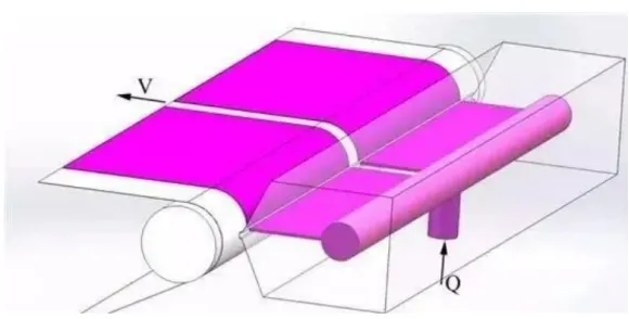
The aluminum-plastic film punching machine actively unwinds the aluminum-plastic film coil and punches out aluminum-plastic film pockets in a sequential manner to meet the size requirements of the battery. The key structures of the aluminum-plastic film punching machine mainly include the unwinding and correcting mechanism, slitting mechanism, punching mechanism, cutting mechanism, etc.
① Unwinding and Correcting Mechanism: The unwinding and correcting mechanism is the front section of the aluminum-plastic film punching machine. It is responsible for loading, changing, and unwinding the aluminum-plastic film, as well as real-time correction of the aluminum-plastic film during normal operation.
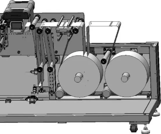
The unwinding and correcting mechanism consists of an air expanding shaft, aluminum-plastic film positioning mechanism, active unwinding mechanism (including motor, reducer, etc.), tension control system, material receiving platform, correction system, etc. Its functions and actions are as follows: manual loading, cylinder positioning of the material roll, photoelectric sensor detection of the presence of the material, manual belt feeding platform with aluminum-plastic film cutting knife and belt pressing plate, and a negative pressure dust suction device below the belt feeding platform. The tension of the aluminum-plastic film is adjusted by a tension controller and magnetic powder brake to maintain a constant tension and a consistent feeding direction. It has a dual unwinding structure to ensure timely operation and efficiency of the entire production line. The unwinding and correcting mechanism is shown in the accompanying figure.
The relevant accuracy parameters of the unwinding and correcting mechanism are as follows:
Tension range: 0-100N
Tension control accuracy: ±3N
Roll diameter detection: Detection range ≥ 400mm, detection accuracy requirement ±0.1mm
To ensure that the aluminum-plastic film is not damaged during transportation, special treatment and processing have been applied to the guide rollers. The guide roller is made of black hard-anodized aluminum alloy A6061, with a coating thickness greater than 4μm and a surface roughness of Ra0.8. The service life can exceed 3 years (while ensuring equipment efficiency, utilization rate, and product qualification rate). Low-friction bearings are used for the roller shaft to minimize rotational resistance.
② Slitting Mechanism: The slitting mechanism mainly consists of linear bearings, columns, cylinders, cutting blades, and blade fixing plates. Its main functions and actions are as follows: before punching the pockets, it is used to release stress by slitting between the two layers of aluminum-plastic film. The cutting blade uses an art knife blade for easy procurement and preparation. When the material is in place, the vacuum suction of the platform is activated, and the upper cylinder drives the cutting mechanism to slit the film. The cutting mechanism has a dust suction cover, which can negatively suck the dust generated during the cutting process, ensuring that the cutting waste and dust are effectively removed. The suction airflow speed requirement is ≥15m/s. The pre-cutting position accuracy is 0.3mm, and the cutting length adjustment range can be selected as needed. The slitting mechanism is shown in the accompanying figure.
The slitting mechanism prepares for the punching of the aluminum-plastic film by cutting slits on the aluminum-plastic film.
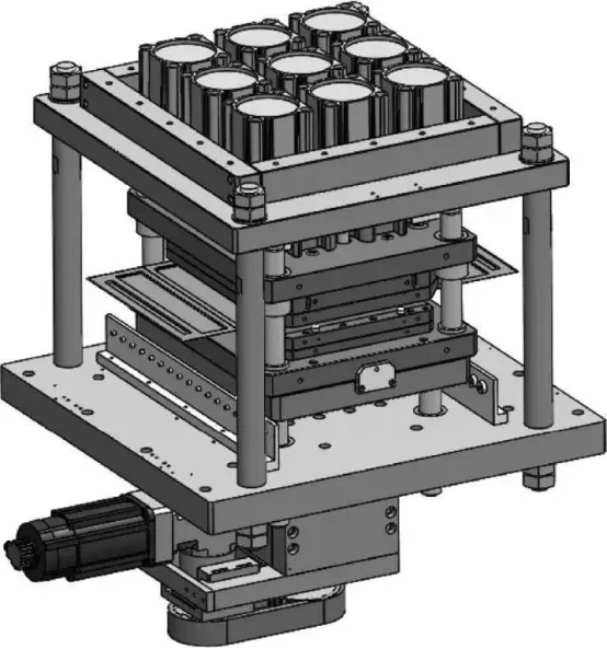
③Pit punching mechanism. The punching mechanism is mainly composed of shell punching mold, servo motor, reducer, ball screw, cylinder, guide shaft, etc.
The pit punching mechanism uses multiple cylinders to compress the aluminum-plastic film, and a servo motor drives the ball screw to punch the pit. The depth can be freely set through pouchware, with a setting range of 2 to 12 mm. The pressing force of the aluminum-plastic film is adjusted by the servo. The mold has the function of punching the positioning holes. It uses a double-pit punching method. The dimensional accuracy of the punching shell can be controlled within ±0.1mm. The positioning pin holes are punched by a cylinder, and the punching accuracy is high. ±0.1mm, pin hole waste is discharged from both sides of the lower mold plate. Both sides of the equipment punching mold are equipped with gratings (perpendicular to the belt conveying direction). When foreign matter is detected, the alarm will beep and the machine will stop. The maintenance is equipped with safety protection functions to prevent maintenance personnel from being trapped by the mold. harm.
The punching mechanism has mold changing requirements, so each punching machine is equipped with a mold trolley to facilitate mold changing.
The punching mechanism is used many times, so material selection is very important. There are mainly the following material types: bottom plate 45# tempered + nickel plating, top plate 45# tempered + nickel plated, main column 45# tempered + chrome plated, upper template SKD11+quenching+nitriding, concave mold SKD11+quenching+nitriding, punch KD11+quenching+nitriding, punch fixed plate 45#+nickel plating. The pit punching mechanism is shown in Figure.
④Cutting Mechanism. The cutting mechanism mainly consists of guide rods, cutting blades, blade fixing seats, upper cylinders, lower cylinders, dust removal mechanism, etc. Its function and action are to cut the aluminum-plastic film into fixed lengths, with a dust removal device during cutting. The cutting blade typically has a lifespan of 300,000 to 500,000 cuts (with a lifespan reminder alarm) and can be sharpened more than 10 times. The cutting edge is equipped with a dust suction system during cutting. The suction airflow speed requirement is ≥20m/s, and the cutting accuracy for the aluminum-plastic shell is ±0.2mm. The cutting mechanism is shown in the accompanying figure.
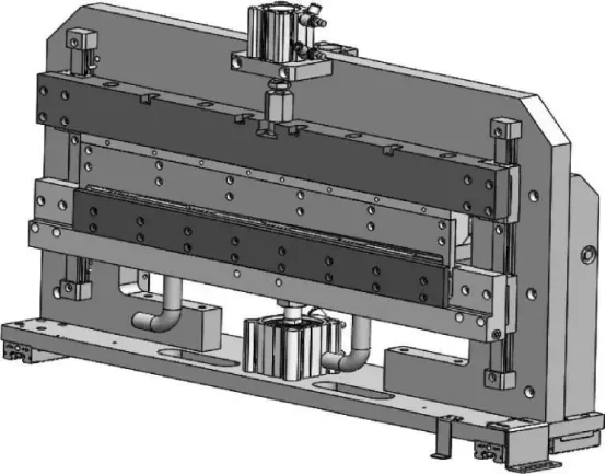
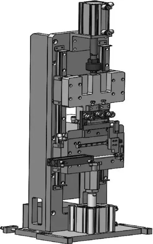
(3)Packing machine
The packaging machine assembles the battery core welded by the tab welding machine and the aluminum-plastic film stamped by the punching machine into a preliminary battery form. The key structures of the packaging machine mainly include the packaging machine clamp, folding mechanism, cutting mechanism, top/side sealing mechanism, etc.
①Packaging machine fixture. The packaging machine fixture is an important carrier for the assembly of aluminum-plastic film and battery cells to complete various processes. It consists of gear racks, angular bearings, upper cavity, lower cavity, suction cups, positioning blocks, etc. Its working principle is that the lower cavity is fixed on the bracket, and the vacuum suction cups are reasonably distributed; the upper cavity is flipped by the fixture flipping mechanism through the rack and pinion, which can achieve the three position requirements of opening, closing, and maintaining, and the vacuum suction cups are reasonably distributed; aluminum film After being placed into the mold cavity, the vacuum suction cup works to determine the position of the aluminum film, and the position of the aluminum film remains unchanged during the flow of each station. Since the aluminum-plastic film is a pouch body, in order to ensure the relative size position between the aluminum-plastic film pit and the battery core, the upper and lower cavities are processed by copying the outer dimensions of the battery core, and the processing accuracy can reach ±0.2 mm, in order to make the clamp as lightweight as possible and ensure the strength requirements, the material is generally A6061 and surface oxidized, which is durable. After folding, the edge alignment of the aluminum film is ±0.2mm. Packaging machine fixture as shown in the figure.
The folding mechanism mainly consists of lifting cylinders, advancing/retracting cylinders, linear guides, folding plates, etc. Its main function and action are as follows: the lifting cylinder remains in the top position, and the advancing/retracting servo pushes the folding plate to the position directly above the folding line of the aluminum film. The lifting cylinder then moves downward to press the aluminum film, aligning the edge of the folding plate with the folding line of the film. The rotary fixture closes, and the advancing/retracting cylinder pulls out the folding plate, fully folding the aluminum film, and moves to the next workstation. At this stage, there are no battery cells inside the aluminum-plastic film. The overall accuracy of the folding mechanism can reach ±0.2mm. The folding mechanism is shown in the accompanying figure.
③Cutting mechanism. The cutting mechanism is mainly used to cut the aluminum-plastic film on the packaging machine. It is mainly composed of an upper cutter driving cylinder, a lower cutter driving cylinder, an upper cutter, a lower cutter, a pressing mechanism, a linear guide rail, a dust removal mechanism, and a pressure regulator. It is composed of valves, etc., and there is a micrometer at the cutting position to facilitate manual adjustment. The function and action are as follows: the turntable rotates one station, the lower cylinder moves, the lower knife lifts up, the upper cylinder moves, the spring pressure plate contacts the aluminum-plastic film and then cuts the aluminum-plastic film, and the cylinder resets at the same time. The cutting mechanism is shown in the figure.
The lower cutting mechanism of the cutting mechanism includes a material receiving box to collect the cut aluminum-plastic film. The cutting mechanism is equipped with a dustproof cover that isolates the cutting area from the external environment during the cutting process. The dustproof cover contains a dust collection device, including a blowing device and a negative pressure dust removal device, ensuring that the cutting waste and dust can be effectively collected. The dust suction airflow speed requirement is ≥20m/s. The top edge cutting accuracy is ≤0.2mm, and the alignment accuracy of the top edge after cutting is also ≤0.2mm. The cutting blade has a lifespan of 300,000 to 500,000 cuts (with a reminder for blade sharpening), and it can be sharpened more than 10 times. A digital micrometer is used to ensure an adjustment accuracy of 0.01mm.
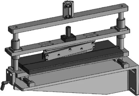
④ Top/Side Sealing Mechanism. The top/side sealing mechanism is primarily used for the top or side sealing of batteries. It mainly consists of a servo motor, ball screw, linear guide, buffering mechanism, tab positioning mechanism, fine-tuning mechanism, NAK80 sealing head, temperature controller, heating tube, thermocouple, and other components. The function and action are as follows: the sealing head is heated using electric heating, and the temperature of the sealing head can be adjusted from room temperature to 250℃. During equipment operation, the overall temperature deviation of the sealing head is less than ±3℃. The power of the heating tube is 1500W, and its lifespan is one year. The temperature control accuracy is ≤5℃. It takes less than 10 minutes to heat from room temperature to 200℃. The sealing head heating seat is designed with a heat-insulating plate for temperature compensation, ensuring that the temperature remains within the required range during high-speed sealing. After the battery rotates to this workstation, the upper and lower servo motors simultaneously drive the ball screw to close the upper and lower sealing heads for thermal sealing. The sealing pressure adjustment range is 0 to 20kgf/cm2. The sealing head is designed with tab slots. The gap between the battery body and the sealing head is adjustable, and there is a digital micrometer for adjustment. The sealing time is adjustable from 0 to 8 seconds with an adjustment accuracy of 0.1 second. The sealing accuracy in the tab area is ±20μm, while in the non-tab area, it is ±15μm. The top/side sealing mechanism is shown in the accompanying figure.