


Slitting, also known as slitting and rewinding, refers to the process of longitudinally cutting a large-width coated film into multiple strips and rewinding them into upper and lower single rolls of a certain width specification. The slitting blades mainly consist of upper and lower circular disc blades, which are installed on the knife shaft of the slitting machine and use the rolling shear principle to slit products such as aluminum foil, copper foil, and positive and negative electrode sheets with a thickness of 0.01-0.1mm. The quality of the slitting blades, the blade angle, and the tension of the film are the main factors affecting the slitting process. After slitting, the electrode sheets should not have wrinkles or powder shedding. High precision is required for the slitting dimensions, and the burrs on the edges of the electrode sheets should be minimal. Otherwise, dendrites may penetrate the separator due to the burrs, causing a short circuit inside the battery.
01 Indicators of slitting equipment
A slitting device, also known as a slitter or longitudinal cutter, refers to a production equipment that cuts lithium-ion battery electrodes, polymer battery electrode sheets, nickel-metal hydride battery electrode sheets, as well as colored metal sheets or coils, into the required size specifications while maintaining a constant tension and meeting certain process requirements. The slitting of battery electrodes requires high dimensional accuracy, and the edges of the electrodes should have minimal burrs. Otherwise, dendrites may penetrate the separator, causing a short circuit inside the battery. The performance indicators of the slitting device mainly include slitting accuracy, slitting equipment precision, and the range of blade and die adjustments.
- Slitting accuracy
After slitting, the longitudinal burrs of the electrode should be ≤7μm, and the transverse burrs should be ≤12μm. There should be no delamination or wrinkles at the cut edges of the electrode. The geometric dimensions should meet the linear tolerance requirements of battery manufacturing processes. This mainly refers to the size tolerance and runout of the knife shaft and slitting blades, as well as their coaxiality.
- Slitting and installation accuracy
The precision of the idler rollers and the blade module during the no-load testing after the assembly and debugging of the slitting equipment mainly refers to the following criteria:
Idler roller surface roughness: Ra ≤ 0.4.
Idler roller cylindricity: ≤ 0.03mm.
Total runout of the idler roller after installation: ≤ 0.05mm.
Runout of the blade module assembly: ≤ 10μm.
- blade adjustment range
The range of adjustable distance between the upper and lower blades of the slitting equipment at the cutting material section.
02 The composition and key structure of slitting machine
2.1 Composition of slitting machine
The slitting equipment mainly consists of unwinding device, unwinding tension control, unwinding edge alignment control, web guiding, CCD appearance defect detection system, slitting, post-slitting width detection system, dust removal, rewinding tension detection, labeling device, rewinding device, and electrical system.
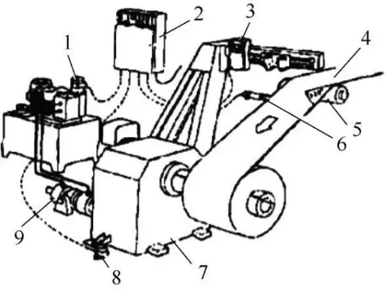
The standard configuration of a fully automatic lithium battery slitting equipment is vertically mounted on the frame. It uses a dual-slip differential shaft with the same direction center winding method for both upper and lower rolls. The clamping of the rewinding and unwinding, as well as the actions of the blade module and pressure rollers, are all pneumatically controlled, making the operation simple and fast. It is driven by a single motor with frequency conversion drive and synchronous belt transmission, ensuring smooth and reliable operation with low noise. The unwinding is controlled by a magnetic powder clutch brake, which provides high tension control accuracy, fast response, and a wide adjustable range. The composition of the slitting equipment is shown below.
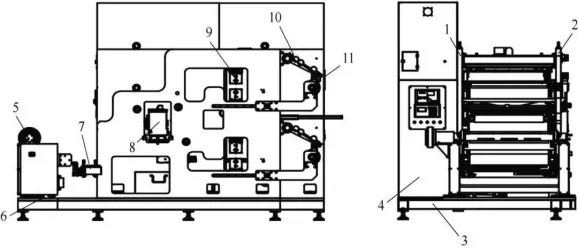
1 – Rear wall panel;2 – Front wall panel;3 – Base;4 – Electrical cabinet;5 – Unwinding device;6 – Edge alignment device;7 – Web guiding platform;8 – Slitting blade;9 – Powder brushing device;10 – Rewinding pressure roller device;11 – Rewinding slip differential shaft device
- – Machine body: Made of high-quality carbon structural steel, it is used to support the frame and electrical cabinet of the slitting equipment. The front and rear wall panels are connected by connecting beams and vertically fixed on the base.
- – Unwinding device: The unwinding is done using an air expanding shaft method. By connecting a magnetic powder brake to the end of the unwinding air expanding shaft, a controllable resistance opposite to the traction direction is applied to achieve unwinding tension.
- – Edge alignment device: It adopts a single inductive probe edge detection for edge alignment. A high-precision edge alignment system is used with an alignment accuracy of ±0.1mm and an alignment stroke of ≥120mm. The sensor position adjustment mechanism is adjusted using a screw and is equipped with a digital display scale and a handle-type locking mechanism.
- Belt Feeding Platform: The gap width of the belt feeding platform is 1mm, with a depth greater than 10mm. The pneumatic pressure rod presses the contact plate. A 5.0mm black steel plate is added to the belt feeding platform, along with a scale ruler. The reference point “0” on the scale corresponds to the width of the gap sleeve between the reference point of the cutting die. The material joining process is done manually. It is necessary to ensure that the distance between the belt feeding platform and the pressure bar is 10mm when the contact plate is properly feeding the belt. Additional safety measures are implemented. If the pressure rod is in the downward position when starting the machine, an alarm and prompt function must be activated, and the alarm must be cleared before the machine can be started.
- – Slitting Die: The clearance between the upper blade and lower blade is conveniently fixed. The cutting die adopts a single-axis drive. The two main shafts are made of 40Cr material, and the base plate and support are made of S136 steel. The surface is hardened with a hardness of HRC50 or above. The overall appearance of the cutting die should be free from rust stains. The scale indication on the adjustment roller for the cutting die entrance is required. The diameter of the feeding roller is φ50mm. When the lowest point of the roller is at the same horizontal position as the highest point of the lower blade, the scale indication is zero. Adjusting upward is indicated as positive, and adjusting downward is indicated as negative. The scale on the adjustment roller of the cutting die should be made with a range of ±5mm. The adjustment roller is made of aluminum alloy, and the surface is treated with brown anodizing, with a hardness not less than HRB300. The two end supports adopt a screw structure and can be adjusted up and down. The scale indication is zero. The adjustment of the diversion roller relative to the zero position is indicated by positive and negative angles, with an adjustment range of ±3°.
- – Powder brushing device:The device uses a detachable brush roller with a clamp-style installation. The shaft hole is fixed, and the drive is achieved by a pull-pin mechanism, making it easy to assemble and disassemble. The bristles of the brush roller are made of soft nylon bristles to prevent damage to the contact plate due to excessive hardness. The brush roller adopts a winding-type bristle placement, ensuring a high bristle density for effective dust removal. The brush rotates in the opposite direction of the contact plate movement to enhance the dust removal effect. During operation, the left and right brushes of the dust removal device are embedded into each other to ensure effective contact between the bristles and the contact plate, applying certain pressure while maintaining sufficient elasticity to ensure the effectiveness of dust removal. The depth at which the two brushes are embedded into each other is 2 to 3mm (controlled by adjusting the thickness of the sealing material on the edge of the dust removal box). The center distance between the two brushes needs to be indicated by a scale. The brush can be adjusted up and down by 50mm to facilitate threading, and there is a precise adjustment position at 10mm, which is beneficial for adjusting the dust removal effect. The brush rotation speed is adjustable from 0 to 300r/min.
- – Rewinding pressure roller device: There is a set of upper and lower rewinding shafts with pressure roller mechanisms. The surface of the pressure rollers is chrome-plated or treated with ceramic coating to prevent edge flipping after slitting.
- – Rewinding slip differential shaft device: There are two upper and lower rewinding slip differential shafts, which facilitate the winding with differential speed. It is equipped with intermediate layer plates and allows for quantitative setting of tension multiplied by the number of strips. It automatically adjusts the tension base according to different slitting widths, and can set the tension base by itself to ensure constant and stable tension, preventing belt breakage during continuous slitting.
2.2 Key structures of slitting machine
The key components of the slitting equipment include the constant tension control mechanism for unwinding and rewinding, the slip differential shaft mechanism, and the edge alignment mechanism.
- Constant tension control structure
①Constant tension control principle.The principle of constant tension control is essential for the unwinding and rewinding processes in slitting operations. As the unwinding diameter decreases and the rewinding diameter increases, the tension will continuously change due to the constant motor speed control. This variation in tension can lead to material wrinkling or breakage if the tension is too low or too high, respectively. To avoid these issues, it is necessary to maintain a constant tension during the unwinding and rewinding process.
The essence of constant tension control is to adjust the motor’s output torque as the diameter changes while keeping the tension unchanged. Motor torque control is achieved through a frequency converter and a three-phase asynchronous motor. The Delta V series frequency converter provides three analog input ports: AUI, AVI, and ACI. These ports can be defined for various functions, with one serving as torque reference and another as speed limitation.
A voltage range of 0-10V corresponds to an output range of 0 to the motor’s rated torque. By adjusting the voltage within the 0-10V range, the constant tension control can be achieved.
- Calculation of tension and torque. From the kinetic analysis in Figure below:
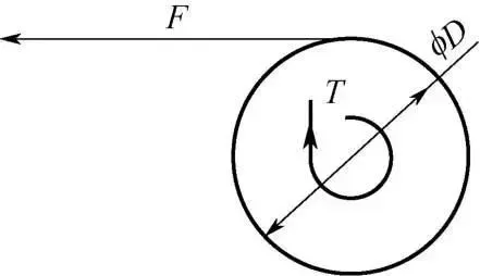
FD/2=Ti
In the equation, F represents tension, D represents diameter, T represents motor torque, and i represents the gear reduction ratio.
The expression for motor rated torque is:
T = 9550P/n
In the equation,T represents the motor’s rated torque in Newton-meters (N·m),
P represents the motor’s rated power in kilowatts (kW), and n represents the motor’s rated speed in revolutions per minute (r/min).
③ Calculation of Motor Synchronous Speed:
The calculation for the synchronous speed of the motor is as follows:
n = 60f/p = 60 × 2/2 = 60 r/min
In the equation,f represents the power supply frequency in Hertz (Hz),n represents the speed of the rewinding motor in revolutions per minute (r/min), and p represents the number of motor pole pairs.
④Speed operation.When using tension control in the system, it is necessary to limit the speed of the slitting machine to prevent runaway. The expression for the running speed V of the rewinding is as follows:
V = πDn/i
In the equation,V represents the running speed of the slitting machine in meters per minute (m/min),D represents the maximum diameter of the rewinding in meters (m),n represents the speed in revolutions per minute (r/min), and
⑤Automatic tension controller.The automatic tension controller consists primarily of a tension sensor, high-precision A/D and D/A converters, a high-performance microcontroller, and other components. This automatic constant tension controller operates by comparing the measured tension of the web material from the tension sensor with the target tension setpoint. It then utilizes PID calculations performed by the microcontroller to automatically adjust the D/A output, thereby altering the excitation current of the magnetic powder clutch/brake or the torque of a servo motor. This ensures a constant tension in the web material. The automatic tension controller can be widely used in various applications that require precise measurement and control of tension. It offers flexibility in operation and has a wide range of applications. It allows for seamless switching between automatic and manual modes, enabling operators to switch between these modes based on their specific requirements.
⑥Rewinding taper tension.In the slitting and rewinding process of polarizing film, the common control method is to adopt constant tension winding. This means that the unwinding machine maintains a constant tension throughout the entire process, including the start of winding, continuous winding, and end of winding. However, when winding the material onto a core or mandrel, there is a noticeable reactive force exerted by the core. If constant tension winding is applied, it can easily result in the phenomenon of the film protruding at the center of the roll, and it may even damage the equipment.To address this issue, a tapered tension control scheme can be employed. This approach greatly alleviates the aforementioned problem. The tapered tension curve, as shown in Figure below, resembles a cone with a pointed top. It creates higher tension at the center of the roll and gradually decreases the tension toward the outer layers as the material roll diameter increases. By controlling the tension, a “tighter on the inside, looser on the outside” winding of the material can be achieved, meeting the process requirements for material winding.
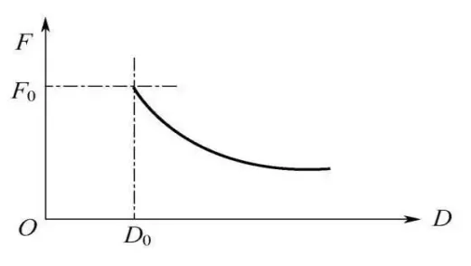
The tension taper formula is expressed as follows:
F = F0 × [1 – K(1 – D0/D)]
In the equation,F represents the actual output tension in Newtons (N),F0 represents the set tension in Newtons (N),K represents the tension taper coefficient,D0 represents the minimum diameter in meters (m), and D represents the current diameter in meters (m).
2)Alignment correcting
①The phenomenon of “deviation”.During the slitting and rewinding process of polarizing film, various factors such as uneven coating, uneven longitudinal tension, irregular edges of the film, misalignment between conveying rollers, and excessive friction between the conical film and the roller surface can cause the film to experience “deviation” during transportation. To prevent this deviation phenomenon, an edge alignment correcting is installed on the slitting and rewinding equipment.
②Correction methods.According to the installation position of the correction equipment, it can be divided into two types: bilateral correction and unilateral correction.
Dual-edge correction In particular, for polarizing films with uneven edges, misalignment, or a tower shape, or when it is difficult to align the film with the centerline of the machine during unwinding, dual-edge correction devices are commonly used on unwinding machines. There are generally two forms of dual-edge correction.
One method is the dual-detection head system, also known as Center Position Control (CPC), as shown in the Figure below. Two sets of detection heads are symmetrically positioned along the centerline of the machine. They are driven by a stepper motor through a bidirectional lead screw, allowing synchronous inward or outward movement. When the film enters the machine, the detection heads move inward. If only one of the heads detects the edge of the film, it indicates that the film has deviated in that direction, and a signal is sent to move the unwinding machine and adjust the film’s position until both detection heads detect the film’s edges and output equal signals. At that point, the detection heads and unwinding machine stop moving, and the film is in the center position. The advantage of this method is that it automatically centers the film during the unwinding process, without the need to consider the width of the material.
The other method is Edge Position Control (EPC), which controls the position of the film’s edges by detecting them. The detection head frame is mounted on the transmission side of the machine. The positions of the detection heads are pre-set based on the width of the incoming material. When the unwinding film enters the machine, the detection heads send signals based on the extent of coverage (fully covered, fully exposed, or partially covered) by the film. The unwinding machine moves to ensure that one side of the film’s edge remains in a partially covered position by the detection head. The advantage of this method is that it only requires a single detection head, making the device relatively simpler. However, the original position of the detection head needs to be adjusted in advance based on the different widths of the material before operation.
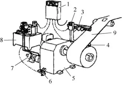
1—Control cabinet;2—Position control detector;3—C-shaped frame;4—Transmitting light source;5—Unwinding machine;6—Center position detector;7—Moving hydraulic cylinder;8—Hydraulic station/servo valve;9—Polarizing film
Unilateral correction:For polarizing films with relatively even edges, single-edge correction is commonly used. Films with smooth edges are less prone to damage during transportation and handling. To achieve uniform winding, a single set of detection heads is used to detect the film’s edges. The position control detector can be mounted on an arm extending from the unwinding machine, and it moves along with the rewinding machine. Alternatively, a separate head holder can be installed near the exit deflection roller of the machine. A set of lead screws driven by a stepper motor moves the detection head or the entire head holder, which includes a position sensor. The working process of these two methods is as follows: When the film is loaded onto the winding core and clamped, the detection head moves in until it detects that the edge of the film partially covers the light source. At the same time, the closed-loop control system is automatically engaged. As the position of the film’s edge changes, the detection head continues to follow and inputs the offset value into the control system. This causes the unwinding machine’s edge correction hydraulic cylinder to move in the same direction and the same distance, ultimately achieving a uniform rewinding result.
1—Hydraulic station/servo valve;2—Control cabinet;3—Position control detector;4—Polarizing film;5—Deflection roller;6—Transmitting light source;7—Rewinding machine;8—Center position detector;9—Moving hydraulic cylinder
- Sliding shaft slitting structure
①Working principle.The slip shaft is based on the principle of slippage of various slip rings on the shaft to maintain tension balance among multiple rolls of material on the shaft, facilitating the process of slitting and rewinding. The main purpose of the slip shaft is to adjust the tension of the material during the rewinding process. By maintaining appropriate tension on all rolls during the operation of the shaft, the slip shaft greatly improves the yield and reduces production costs, especially in the application of battery polarizing film. It is an important component of the lithium battery slitting machine (slitter).
②Main structure.The slip shaft has a special structure consisting of multiple slip rings. During operation, the slip rings are controlled to slip with a certain torque value, precisely compensating for the speed difference generated. This allows for accurate control of the tension of each roll of material, ensuring constant tension winding and guaranteeing the quality of the winding. It can be applied within a wide range of tension, from very low to high levels. The slip shaft is suitable for applications that require high speeds, large material thickness variations, multi-stage tension control, high precision tension control, and neat end-face winding. It is particularly well-suited for use in dual-axis center winding slitting machines.
③Representative products.Japan’s Tōshin slip shaft and Nishimura slip shaft are known for their high control precision, although they come at a relatively higher cost. The main unit of the slip shaft is the pneumatic expansion unit, which consists of a chamber, inclined bottom plate, piston, air seal, bearings, springs, and expansion plates. Each unit has a length of 40mm, and the 18 units can be interchanged and replaced independently at any position, thereby improving the lifespan and ease of maintenance.
④Material technology.The main body of the product is made of quenched and tempered mold steel or aluminum alloy with hard anodized coating. The rubber expansion plates are made of high-temperature and wear-resistant polyurethane material and are vulcanized accordingly, depending on the maximum tension requirements. Different sizes of slip shafts can be customized based on specific requirements, including components such as the main shaft, pneumatic expansion unit, expansion plates, springs, and universal joints.
⑤Instructions for use.The slip shaft significantly enhances the speed, rewinding precision, automation level, reduces setup time, and improves user-friendliness of the slitting machine. The application of slip shafts in rewinding greatly improves the yield of quality products and reduces production costs. Our slip shaft ensures the highest quality of material rolls by maintaining appropriate tension on all rolls during operation.
2.3 What is the difference between electrode sheet slitting and other ordinary metal plate slitting?
Compared to the cutting process of metal sheet materials, the cutting method for lithium battery electrode discs has completely different characteristics:
During electrode disc cutting, the upper and lower circular blades have a negative rake angle, similar to the blades of scissors, with a very small edge width. There is no horizontal gap between the upper and lower circular blades (parameter c in the diagram is equivalent to a negative value), but rather, the upper and lower blades come into contact with each other and exert lateral pressure.
In sheet material cutting, there are rubber support rollers both above and below, which balance the shear force and shear torque generated during cutting, thereby avoiding significant deformation of the sheet material. However, in electrode disc cutting, there are no upper and lower support rollers.
The coating on the electrode disc is a composite material composed of particles and has little plastic deformation ability. When the internal stress generated by the upper and lower circular blades exceeds the cohesive force between the coating particles, cracks form in the coating and propagate, leading to separation.
2.4 What are the key points of slitting?
1. Influence of physical and mechanical properties of materials
In general, materials with good plasticity tend to delay the appearance of cracks during shear, resulting in a greater depth of material being sheared and a larger proportion of bright shear zone. On the other hand, materials with poor plasticity are more prone to fracture under the same parameter conditions, resulting in a higher proportion of tearing zone in the fracture surface and a naturally smaller bright shear zone.
- The influence of upper and lower pairs on the lateral pressure of the tool
In the cutting process of electrode discs, the lateral pressure exerted by the tool is one of the key factors affecting the cutting quality. During shearing, the alignment of the upper and lower cracks on the fracture surface and the stress-strain state of the shearing force are closely related to the magnitude of the lateral pressure. If the lateral pressure is too low, defects such as uneven cutting surfaces and material loss may occur during the cutting of electrode discs. Conversely, if the pressure is too high, the tool is more prone to wear, resulting in a shorter lifespan.
- The influence of the overlap amount of the upper and lower paired tools (parameter δ in the above figure)
The setting of the overlap amount is mainly related to the thickness of the electrode disc. A reasonable overlap amount is beneficial for tool engagement and has an impact on the quality of the cut, the size of burrs, and the rate of tool edge wear.
- Influence of bite angle (parameter α in the above figure)
In disc cutting, the bite angle refers to the angle between the cutting segment and the centerline of the sheet being cut. As the bite angle increases, the horizontal component of the cutting force also increases. If the horizontal force exceeds the feed tension of the electrode disc, the sheet material may either slip or arch in front of the circular blade, making it impossible to perform the cut. On the other hand, reducing the bite angle requires an increase in the diameter of the blade, which in turn requires larger dimensions for the slitting machine. Therefore, balancing the bite angle, blade diameter, sheet thickness, and overlap amount must be determined based on the actual working conditions.
2.5 Defects
The main defects in electrode sheet slitting include the following:
- Burr
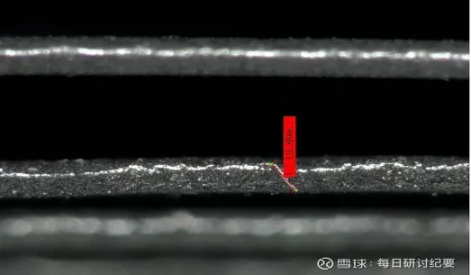
Burrs, especially metal burrs, pose a significant risk to lithium batteries. Larger metal burrs can directly penetrate the separator, causing a short circuit between the positive and negative electrodes. The slitting process of electrode discs is the main source of burr generation in lithium-ion battery manufacturing. The image above shows the typical morphology of metal burrs generated during the cutting of electrode discs. Due to unstable tension control during slitting, secondary sliting occurs, resulting in foil burrs with dimensions exceeding 100μm. To avoid this situation, it is crucial to find the most suitable lateral pressure and tool overlap based on the properties and thickness of the electrode disc during tool adjustment. Additionally, chamfering the blade and adjusting coil tension can help improve the edge quality of the electrode disc.
2.wavy edge
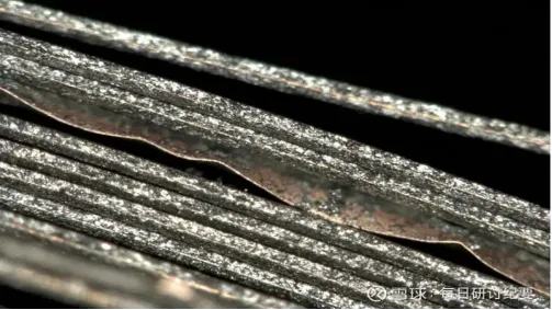
During the slitting of electrode discs, improper tool overlap and pressure can result in wavy edges and coating delamination at the cut. When wavy edges occur, there can be edge deviation and vibration during the slitting and winding of the electrode discs, leading to a decrease in process accuracy. Additionally, it can have a negative impact on the final thickness and appearance of the battery.
03 Selection and application cases of slitting machine
(1) Equipment Selection:
The selection of a slitting machine should consider factors such as cutting accuracy, slitting equipment precision, and the range of blade adjustment.
(2) Application Case:
Taking the ZY750-C600-C50 slitting machine from Chaoyang Machinery Manufacturing Co., Ltd. as an example, it is a C-type fully automatic lithium battery slitting equipment with a maximum incoming width of 750mm, a rewind and unwind diameter of ϕ600mm, a minimum slitting width of 30mm, and a running speed of 50m/min. The equipment is equipped with a CCD detection system to detect issues such as damage and wrinkles on the electrode disc.
04 Use and maintenance of slitting machine
(1) Use of Slitting Machine:
Taking the example of the Model 65 slitting machine from a certain company, the usage of the slitting machine is described. Figure below shows the main interface of the system. By clicking on “Enter System,” you can access the system. The operational button interface is shown in Figure below, and the explanations of each functional button are as follows.

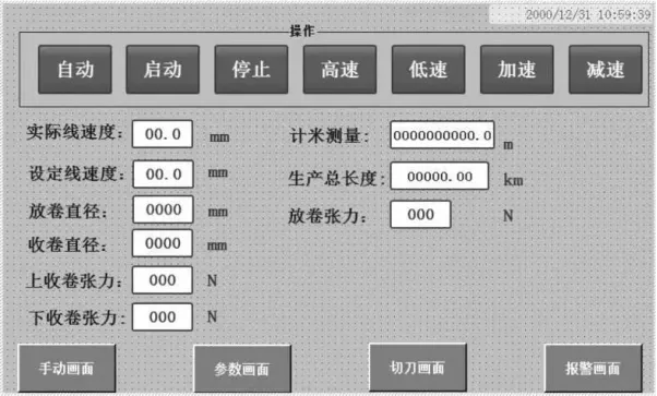
Length Measurement: The length produced in automatic operation mode can be reset to zero.
Total Production Length: The accumulated length during automatic operation mode, which cannot be reset to zero.
Set Line Speed: The current running speed set by the user through the HMI (or speed controller).
Actual Line Speed: The real-time speed at which the machine is currently running.
Speed Increase (+): Pressing this button increases the current speed by 1m/min (the increment value can be set).
Speed Decrease (-): Pressing this button decreases the current speed by 1m/min (the decrement value can be set).
Unwind Tension: The real-time tension detected by the unwind tension sensor.
Rewind Diameter: The real-time diameter of the rewound material.
Upper Rewind Tension: The real-time tension of the upper rewind.
Lower Rewind Tension: The real-time tension of the lower rewind.
Parameter Screen: Accessing the parameter screen to set parameters such as traction speed, unwind tension, rewind tension, traction torque, etc.
Cutter Screen: Accessing the cutter screen to set the cutter usage length, reset various length values, and determine whether to enable the cutter.
Manual: Accessing the manual debugging operation screen to manually control functions such as unwind, rewind, brush, and blade stop/start.
Auto: Selecting the automatic mode.
Start: Starting the entire line (valid in automatic mode).
Stop: Stopping the entire line (valid in automatic mode).
High Speed: Running the machine at high speed.
Low Speed: Running the machine at low speed.
(2) Installation and Commissioning of the Slitting Machine:
The operation of the slitting machine involves three steps: tension adjustment, EPC alignment correcting adjustment, and commissioning of the rewind electrical proportional valve. The commissioning of the electrical proportional valve is a critical step, and the procedure is as follows:
- Connect the 24V power supply according to the wiring requirements.
- Supply compressed air to the proportional valve within the range of 0.5-0.65MPa.
- Press and hold the “Unlock” or “Lock” button for more than 3 seconds until the indicator light blinks.
- Press the SET button intermittently to display GL.9/F01/F02 (F01 = lower limit, F02 = upper limit).
- When F01 is displayed with a flashing number, press the decrease or increase button to decrease or increase the number. Generally, F01 = 0.15-0.25.
- When F02 is displayed with a flashing number, press the decrease or increase button to decrease or increase the number. Generally, F02 = 0.45-0.50.
- Press the SET button after completing the debugging process.
(3) Precautions and Maintenance for Operating a Slitting Machine:
1)Operators must receive training before starting work and be familiar with the operation of the slitting machine, equipment performance, and general maintenance methods. Personnel who are not trained for this job should not operate the machine.
2)Take necessary labor protection measures before starting the machine. Prepare auxiliary tools and materials (such as knife adjustment tools, required cartons, paper tubes, cutting knives, tape, etc.) and place them in a suitable position on the machine.
3)Ensure that the equipment is in a safe condition. Turn on the electrical switch, check for any missing phases in the circuit, and ensure that the air circuit is unobstructed. Run the machine in a trial operation and check if the electrical, pneumatic, and mechanical equipment are functioning properly.
4)Check whether the mechanical safety devices are in place. During operation, prevent crushing, scratching, or getting caught in rotating gears, chains, and rollers.
5)Knife adjustment: Adjust the knife distance accurately according to the job requirements and pay attention to the direction of the blade. If necessary, remove the bottom knife and rearrange it. Repair or replace the blade if it is damaged or not sharp.
6)Check the connection of the static elimination device and the grounding wire of the machine to ensure that static electricity is eliminated during operation. Place waste paper under the machine to prevent dust accumulation.
7)Pay attention to safety when feeding materials. Push the material to the appropriate position for inflation and pay attention to the rotation direction of the material. Do not load the material in reverse.
8)Material threading and edge alignment: Thread the material from the unwind to the rewind according to the direction set by the equipment, adjust the edge alignment, and ensure that both sides of the finished product have adhesive. Pay attention to the edge alignment during feeding. It should be aligned in the middle of the alignment stroke. If the material cannot be cut to the edge when it exceeds the stroke, take immediate action to resolve the issue.
9)Place the required paper tube on the rewinding shaft and align the material. If double-sided tape is required, ensure that it is properly applied. Adjust the appropriate tension for rewinding and unwinding, and perform edge cutting and rewinding.
10)During the rewinding process, carefully inspect the product quality. Avoid rolling in defective or waste products, dirt, or edge trims. Strictly control the length.
11)After shutdown, turn off the power and air supply, and perform necessary cleaning and maintenance on the machine. Avoid using a knife to scrape the transfer roller. Clean any adhesive on the equipment with solvent.
12)In case of any problems during operation, stop the machine for troubleshooting. If it is not possible to stop the machine, handle the situation with caution and reduce the speed if necessary.


