


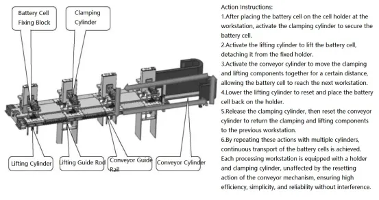
prismatic batteries refer to batteries with aluminum casings. They use laser sealing technology, and the fully sealed aluminum casing technology is already highly mature. It has low requirements for material technology indicators such as gas generation and expansion, making it an early popularized form of power battery in China. Compared to the other two forms of lithium batteries (cylindrical and pouch), prismatic batteries have prominent advantages in market use, including:
① High packaging reliability.
② High system integration efficiency.
③ Relatively lightweight with high energy density.
④ Simple structure and convenient scalability, making it a primary choice for large-capacity individual cells.
⑤ High individual cell capacity, simple system structure, and easy battery management.
01 Main functions and description of equipment
The aluminum casing lithium battery assembly line is used for the mid-stage assembly of power batteries and is an important part of the power battery production process. It has a significant impact on the performance and accuracy of the battery. As a result, the automation level and operational accuracy of this assembly line are increasingly attracting market attention. In this section, we will introduce a highly mature and market-proven battery assembly line that has been recognized and accepted. The assembly line has the following characteristics:
1. Strong compatibility: It can be compatible with various different series of products according to customer requirements.
2. Modular design: Short changeover time, fewer parts, and low cost.
3. High assembly accuracy: Dual positioning using visual and mechanical methods to enhance positioning accuracy.
4. Customization for different cell types and customer-specific process routes to achieve fully automated assembly lines.
5. Reasonable equipment layout: Space-saving, fully automated line, and low labor cost.
6. High manufacturing quality assurance: Full parameter testing and monitoring.
7. Manufacturing guarantee for battery safety and consistency.
This automated production line is used for the automatic assembly of prismatic aluminum-cased lithium-ion power battery cells after winding. The production line mainly consists of the following major components: hot press testing machine, X-ray machine, pairing machine, ultrasonic welding machine, tab welding machine, core alignment machine, film/heat sealing/adhesive machine, pre-spot welding machine for casing, laser lid welding machine, and helium leakage testing machine. It achieves functions such as thermal pressing of battery cells, X-ray testing, pre-welding and pairing of electrode tabs, welding of tab connectors, backside adhesive application, laser welding of cover plates, adhesive application, tab folding and core alignment, encapsulation, casing, and lid sealing welding, enabling full automation throughout the process.
1.2 Future development trends of assembly lines
The aluminum shell (prismatic) battery production line has been in use for a long time, the corresponding technology is very mature, and the existing assembly line is also similar. The future development trend, in addition to continuing to improve materials and finding high-performance cell materials, for battery assembly production lines, high efficiency and low cost are still the future development directions of power lithium batteries. An overview of the existing market development After summarizing, the following points are worthy of attention:
①The performance of the battery body, such as battery size, energy density, multi-tab structure, etc.
②Assembly production efficiency, continuously improve production efficiency while ensuring that equipment costs do not change significantly.
③The automation of battery assembly lines continues to improve, and the production yield is easier to control. The production time of each process is reasonably controlled, thereby effectively shortening the production time of lithium batteries, and greatly improving the problems of high labor intensity for workers and high production costs.
④Better compatibility, suitable for a wider range of products.
⑤ Modular technology is an important way to improve efficiency.
1.3 Design of aluminum shell (prismatic) lithium battery production and assembly line
When designing an aluminum-cased (prismatic) lithium battery production assembly line, different designs are considered based on customer requirements. Taking into account the problems encountered and corresponding practices in the production process, the following aspects are primarily considered:
1. Product process: This includes the size of the battery, tab size, and welding thickness, among others.
2. Factory space: Proper arrangement of the specific positions of production line equipment, optimization of mechanisms, consideration of ergonomics, ease of manual operation, and maintainability.
3. Equipment design: The simpler the structure, the easier the operation.
4. Allocation of production line rhythm: Emphasis is placed on the efficiency of bottleneck workstations. If the efficiency is not met, single workstations can be modified to dual or multiple workstations. High safety performance and first pass yield are also key considerations.
5. Product positioning method: Different product positioning methods are used for different customer requirements, such as side positioning, baseline positioning on two sides, and fixture positioning.
6. Dust prevention device: In cylindrical battery assembly line, each device that requires dust removal is equipped with corresponding facilities, such as dust collectors and brushes.
7. Logistics design within the equipment: This includes internal equipment conveyance and conveyance between equipment.
8. Quality inspection: The entire assembly line includes CCD inspection, cell thickness measurement, insulation inspection, short circuit detection, and more.
9. Consistency in the appearance of the production line: Maintaining the aesthetic appearance of the entire set of equipment.
02 Equipment composition and key structure
The overall layout of the aluminum shell lithium battery assembly line is as follows:
① Dimensions of the entire line: length × width × height = 3700mm × 7000mm × 2400mm (height does not include alarm lights), operating surface height 900mm, equipment spacing 800 ~ 1000mm.
②Appearance: The stress-bearing chassis adopts a square tube welded structure, the upper sealing frame adopts an aluminum alloy profile structure, and is sealed with plexiglass. The entire equipment cover is covered with sheet metal.
③Operation interface: Each device is equipped with an independently operated touch screen, and the touch screens of all devices are embedded.
④ Whole line layout: The layout of the lead shell battery assembly line is shown in Figure .
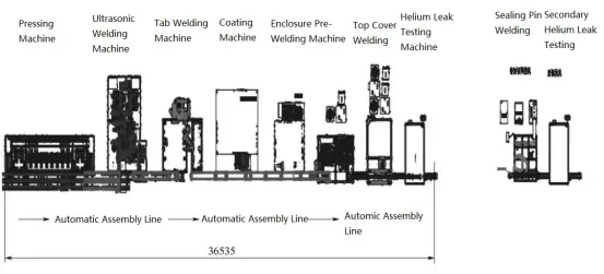
This production line is a fully automated assembly line that includes the entire production process of aluminum-cased batteries, from the winding machine to the helium leak testing machine. The process includes: winding to the hot-pressing conveyor line (with 6 sets of material handling robots on the winding machine) → hot-pressing machine → ultrasonic welding machine → tab laser welding machine → cell packaging machine → enclosure and pre-spot welding machine → lid laser welding machine → air tightness testing machine.
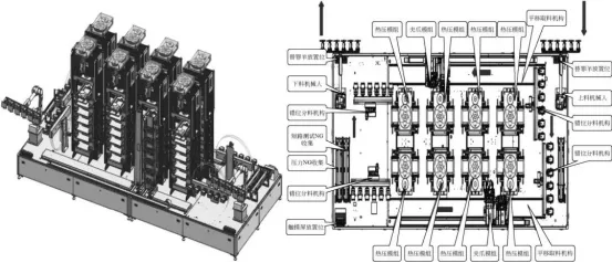
2.1 Hot Pressing Machine
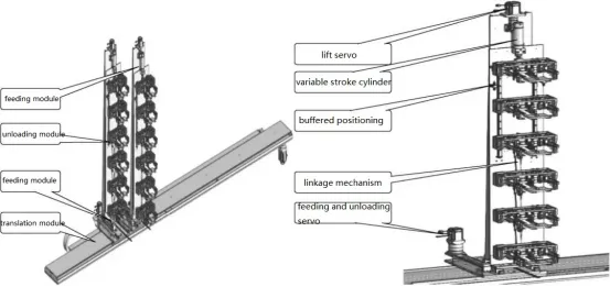
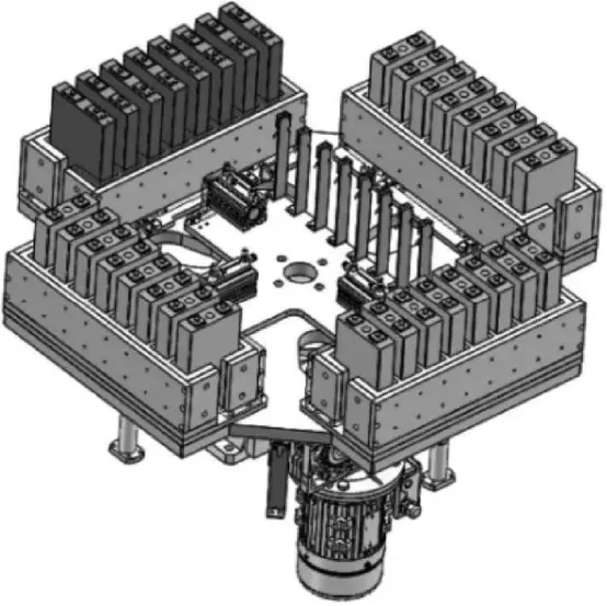
The hot-pressing machine is used for the thermal compression molding of wound battery cells. Its main functions include cell barcode scanning, automatic loading of A/B cells, hot-pressing, Hi-pot testing, and rejection of defective products. The hot-pressing temperature, pressure, time, Hi-pot testing parameters, and results are associated with the corresponding barcode and uploaded to the MES system. The equipment mainly consists of modules for cell loading/unloading, detection, and hot-pressing. This equipment is the first process in assembling aluminum-cased battery cells, and the quality of the hot-pressed cell directly affects the quality of the subsequent processed products. Therefore, the efficiency, working precision, and level of automation of this assembly equipment are crucial considerations.The equipment layout and workflow are as shown in the diagram.
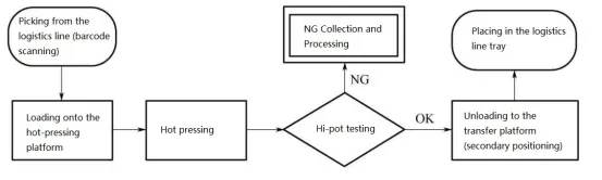
From the diagram, it is clear to see the operation process of the wound battery cells on the hot-pressing machine. During the working process, the equipment performs hot-pressing and subsequent testing of the wound battery cells. The test results, including hot-pressing temperature, pressure, time, and Hi-pot, are uploaded to the MES system for real-time monitoring and feedback. Defective products are rejected to ensure the processing quality.
From the equipment layout diagram, it can be seen that key components such as the loading and unloading robotic arms, transfer conveyors, transfer robots, misalignment separation mechanisms, and hot-pressing modules play a crucial role in the assembly of the semi-finished products. Let’s provide detailed explanations for some of these components.
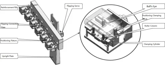
①Dislocation distribution mechanism. Figure shows the misaligned material distribution mechanism. The function of the flip positioning module is: the flip mechanism uses a belt servo drive to realize the flipping of the clamp and the synchronous flip of the connecting plate. The clamp always remains horizontal and the flip is smooth and reliable. The positioning fixture uses a clamping jaw cylinder and a double-link cylinder for clamping and positioning; the contact surface with the battery core uses POM material.
②Move the module up and down. The loading and unloading module is shown in the figure. Its main actions are: translation using a synchronous belt servo module and dual belt drive to increase the smoothness of the movement of the loading and unloading module; the loading and unloading module uses a belt servo for incoming and outgoing materials, and an independent servo Control; the clamping jaws are raised and lowered using a screw cylinder; the pitch change mechanism uses a servo-driven linkage mechanism, using the middle link as the positioning reference to achieve synchronous pitch change. The servo can control the equidistant size of the clamping jaws to achieve different working conditions of the hot press. The position translation module synchronizes the loading and unloading of materials.
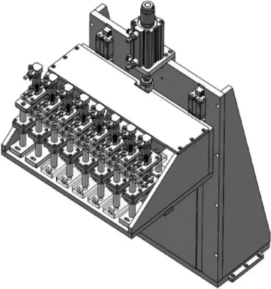
③Hot pressing components. The hot pressing components of the hot press equipment are shown in the figure, and their detailed description is as follows:
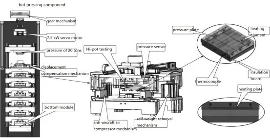
Main components: Boosting cylinder (20 t pressure, 6 layers), heating tube, temperature controller, pressure sensor, etc.
Operating procedure: Perform hot pressing and Hi-pot testing on the battery cells.
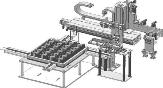
2.2 Ultrasonic Welding Machine
The ultrasonic welding machine mainly completes the ultrasonic welding of battery cells through processes such as cell scanning, automated cell pairing by robotic arms, cell calibration and polarity detection, adapter plate polarity detection and calibration, adapter plate welding fixtures, cell welding fixtures, protective cover placement, ultrasonic welding and dust extraction, weld mark shaping, adhesive application and adhesive inspection, and automatic unloading. This equipment realizes cell scanning, ultrasonic welding, adhesive application, and information binding from cell pairing to encapsulation. It mainly includes functions such as cell scanning upon arrival, cell calibration and feeding, adapter plate calibration and feeding, adhesive inspection, and information binding upload to the MES system.
The gripping mechanism is equipped with a color sensor to identify the polarity tabs of the battery cells, ensuring that the tabs are not paired incorrectly. The battery cells are grabbed by the robotic arm from the incoming conveyor belt. After undergoing secondary positioning, they are placed into the tray, ensuring a misalignment error of ≤±0.2mm for A/B cell polarity tabs. The battery cells are placed in the tray with center alignment. Before placing the cells, the elastic clips around the tray are opened, and then the robotic arm places the cells into the tray, after which the clips close, positioning the cells in the center of the tray.
Equipment composition and key structures
Cell loading module, cell ultrasonic welding cycle line and fixture module, adapter sheet, protective sheet loading module, protective sheet cover loading and unloading module, ultrasonic positive and negative electrode welding module, solder stamping flattening module, battery core pasting module The protective glue module, the battery cell protective glue module, the battery cell unloading module, and glue detection are relatively critical and play a vital role in the entire assembled semi-finished product. Several of these mechanisms are selected for detailed introduction.
①Battery core loading module (as shown in the picture). It has the functions of automatic loading of battery cells, dust removal of incoming materials, anti-fool prevention of incoming materials, buffering of incoming materials, and shortage alarm functions. It also has the function of scanning code to bind battery cells.
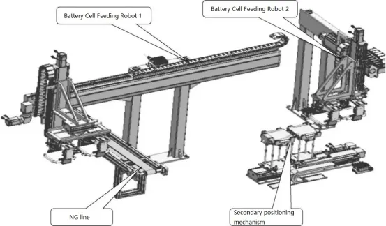
a. Main components: Translation mechanism + lifting mechanism, battery cell gripper, etc.
b. Operating procedure: The battery cell feeding and handling process uses a belt module. Feeding robot 1 grabs a group of battery cells from the pallet on the customer’s logistics line and places them into the secondary positioning mechanism. After the battery cells are secondarily positioned, handling robot 2 grabs the cells and places them onto the cycle line. If during the feeding process, a pair of battery cells is detected to have a single NG (non-good) cell, handling robot 1 will place the NG cell back onto the NG line, while the OK (good) cell will be placed in the pairing mechanism for further matching.
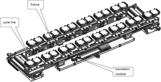
② Battery cell ultrasonic welding cycle line and fixture module.
a. Main components: Cycle line, module, long and short edge positioning blocks, cylinders, guide rails, etc.
b. Operating procedure (functional description without specific operating steps): Handling robot 2 feeds the battery cells into the cycle line fixture, which clamps the cells. The translation mechanism moves the fixture to the next workstation.
The schematic diagram of the ultrasonic welding cycle line is shown in the figure.
③ The module for loading adapter plates and protective films (as shown in the diagram).
a. The loading of copper-aluminum adapter plates includes measures to prevent misplacement or reverse insertion, such as polarity detection, to avoid human errors.
b. The loading of connector plates is equipped with a brush to prevent improper suction or picking up multiple plates. It also includes functions like air blowing and vacuum shaking to ensure proper separation and detection of multiple plates. There is a waste disposal mechanism for storing the rejected multiple plates.
c. The preparation of protective film trays involves manual loading into the clip holder. The suction nozzle picks up a set of protective films each time, depleting the supply at the feeding end. The turntable (or moving module) rotates to the next position to ensure uninterrupted supply of protective films.
d. Key components include servo motor, lead screw, cylinder, and suction cup.
e. The preparation of adapter plate trays involves the suction nozzle picking up a set of adapter plates each time, depleting the supply at the feeding end. The tray rotates to the next position to ensure uninterrupted supply of adapter plates.
f. A single loading can sustain production for 40 minutes.
④ The module for loading and unloading protective film covers (as shown in the diagram).
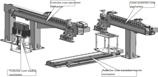
a. Key components: Servo motor, lead screw, cylinder, guide rail, etc.
b. Operating procedure: In the initial state, the protective covers are manually placed into the upper protective cover preparation mechanism. The upper protective cover placement mechanism grabs a set of protective covers and moves them to the upper protective cover workstation, ensuring that all protective cover plates are in a continuous loop on the assembly line. When removing the lower protective cover, the lower protective cover mechanism retrieves the cover from fixture on assembly line 2. The platform moves the protective cover to the protective cover transfer mechanism, which then moves to the upper protective cover position. The upper protective cover placement mechanism retrieves the protective cover and places it into the corresponding fixture on assembly line 1.
c. A single loading can sustain production for 40 minutes.
⑤ Ultrasonic positive and negative electrode welding module (as shown in the diagram).
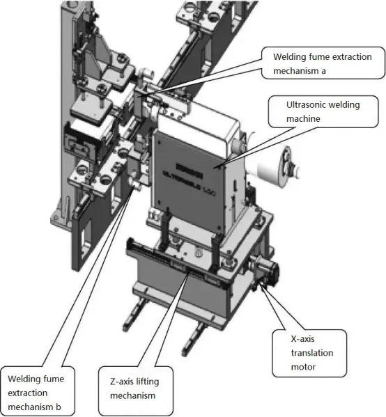
a. Key components: Platform, ultrasonic welding machine, cylinder, etc.
b. Operation process: After fixture positioning, the Z-axis lifting cylinder rises, and the ultrasonic welding head descends to complete the welding process. The X-axis and Y-axis translation is adjusted using servo motors to position the welding machine and facilitate tooling change. The X-axis and Y-axis travel ensure compliance with the dimensional requirements for tooling change.
⑥ Weld impression flattening module (as shown in the diagram). This module ensures that the protective film remains flat and the terminal tabs are not bent. The pressure block is made of wear-resistant material called polyether ether ketone (PEEK).
a. Main components: slide rail, cylinder, etc.
b. Action process: After the clamp on the circulating line body is in place, the avoidance cylinder drives the upper and lower molds to extend forward, then the lower mold is pushed up, the upper mold is pressed down, and the welding mark is leveled. Subsequently, the upper mold moves upward, the lower mold moves downward, and the avoidance cylinder drives the upper and lower molds to retract the position avoidance clamp.
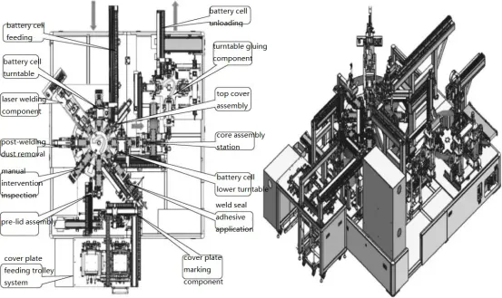
2.3 Adapter plate laser welding machine
1) Equipment composition
The main functions of the adapter plate laser welding machine equipment include automatic loading of the top cover and battery cells, and welding the connecting piece and the top cover into one body through laser welding, automatic unloading after dust removal and glue application, as shown in the figure.
Equipment dimensions: Length × Width × Height = 2800mm × 3800mm × 2300mm.
Appearance: The load-bearing chassis adopts a square tube welding structure, and the upper sealing frame adopts an aluminum alloy profile structure, sealed with organic glass.
Operating interface: The equipment is equipped with an independent touch screen for operation, and all touch screens of the equipment are embedded.
2)Key Structures
From the diagram above, it can be seen that the cover plate feeding mechanism, top cover assembly, laser welding module, post-welding dust removal mechanism, and weld seal adhesive application component are crucial and play a vital role in the assembly of the semi-finished product. We will provide detailed introductions and explanations for some of these mechanisms.
①cover plate feeding mechanism
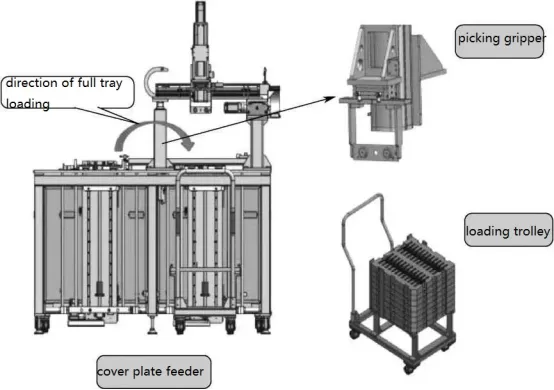
a.Function: The cover plate feeding mechanism achieves the supply of cover plates and includes features such as tray positioning and transfer.
b. Key components: Lifting mechanism, tray positioning mechanism, small cart, etc.
c. Requirements: One-time loading to meet continuous production of the equipment for 30 minutes; one in-use and one spare loading cart, and three unloading carts; tray secondary positioning accuracy of ≤0.1mm.
②top cover assembly
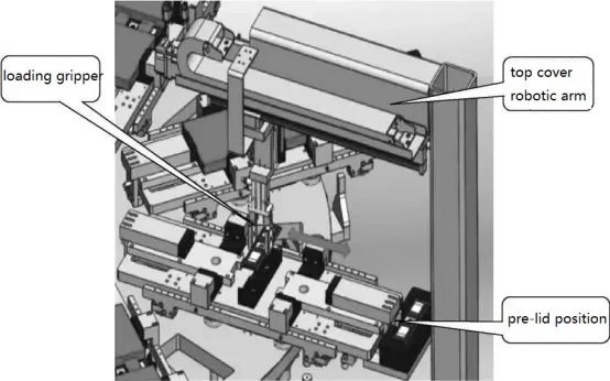
a.Function: To grab the coded cover plate and place it onto the turntable.
b. Key components: Translation synchronous belt module, lifting screw module, gripping claw, etc.
c. Requirements: Reliable grabbing with no material dropping or damage, repetitive precision of the mechanism operation ≤±0.05mm, flexible design of the robotic arm, non-contact parts of the robotic arm that come into contact with the product should use non-contaminating materials.
③ Laser welding module (as shown in the diagram).
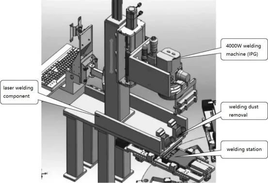
a. Function: To weld the cover plate and tab together using the laser welding machine.
b. Key components: Welding platform, cell carrier, etc.
④ Post-welding dust removal mechanism (Figure 21): The lifting cylinder lowers, covering the welding area to create a sealed space for dust extraction. The suction airflow velocity is ≥12m/s and the velocity is infinitely adjustable within the maximum range.
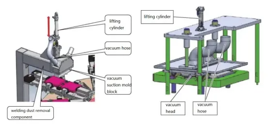
a. Key components: Lifting cylinder, rotary motor, suction port, etc.
b. Operation process: The fixture moves to the dust removal station; the cylinder descends, and the motor rotates to perform dust removal.
⑤ Weld seal adhesive application component (as shown in the diagram).
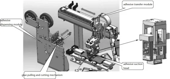
a.Function: Apply protective adhesive on top of the tab welding area.
b. Main components: Glue pulling mechanism, glue cutting mechanism, glue application mechanism, glue roller assembly, etc.
c. Requirements: Adjustable tape length and adhesive placement; vacuum detection and warning for defective backup tape; tape presence detection function; shaping device for the welding area before adhesive application; adhesive application yield ≥99.8%.
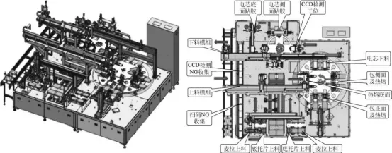
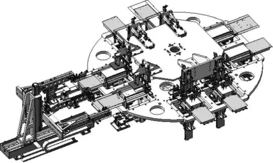
2.4 Film Wrapping Machine
1.Main functions of the equipment:
The film wrapping machine is mainly used for automatic shaping of battery cells, automatic feeding of separator and bottom tray, wrapping the cell with the separator, applying adhesive on the side and bottom surfaces, CCD testing, etc. The equipment layout is shown in the diagram.
Here are the basic specifications of the equipment:
·External dimensions of the equipment: 3100mm × 4000mm × 2300mm.
·Equipment yield: ≥99.8% (excluding incoming defective materials).
·Equipment uptime: ≥98% (referring only to failures caused by equipment-related issues).
2)Key structures
From the layout diagram of the film wrapping machine, it can be observed that the bottom adhesive application mechanism, separator and bottom tray feeding layout mechanism, front wrapping film mechanism, bottom adhesive application mechanism, and side adhesive application turntable mechanism are quite crucial and play a vital role in the assembly of the semi-finished product. Let’s provide detailed explanations for some of these mechanisms.
① Layout of separator and bottom tray feeding (as shown in the diagram).
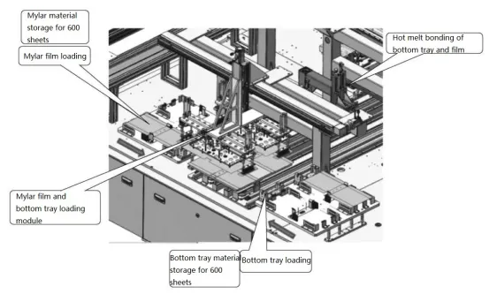
a. Key components: Manual Mylar feeding assembly (1 set), Mylar feeding robotic arm (1 set), bottom tray material box (1 set), bottom tray feeding robotic arm (1 set), Mylar-bottom tray hot melt platform (1 set), hot melt mechanism (1 set).
b. Operation process: The robotic arm places the bottom tray on the hot melt fixture → The Mylar feeding robotic arm places the film on the hot melt fixture → The hot melt fixture is moved to the hot melt station → Hot melting process → Turntable film feeding and unloading robotic arm waits at the retrieval position.
② Front wrapping film station (as shown in the diagram). The layout of film wrapping and hot melt turntable is shown in the diagram.
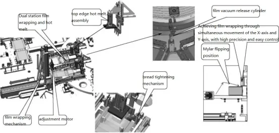
a. Key components: Workstation fixtures (8 sets), hot melt assembly (1 set), film wrapping assembly (1 set), folding film mechanism (1 set), fixture opening mechanism (3 sets).
b. Operation process: Film loading → Cell loading → Bottom surface hot melt → Front film wrapping → Front surface hot melt → Side film folding → Side surface hot melt → Unloading.
③ Bottom adhesive application mechanism (as shown in the diagram).
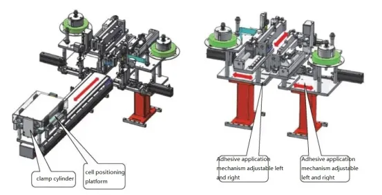
a. There are L-shaped adhesive tapes on both sides of the bottom; the length and position of the tapes can be adjusted, with symmetrical adhesive positions and a deviation of ±0.5mm. The adhesive process should not cause pressure or scratches on the battery cell.
b. Poor adhesive backup can be detected and has a warning function. After adhesive application, the adhesive is inspected for presence or absence using a color mark sensor.
c. Manual adhesive backup is performed by hand.
d. Function: After wrapping the battery cell, adhesive is applied to fix it on the bottom tray in an “L” shape.
e. Key components: Glue roller, adhesive application and cutting assembly, etc.
f. Requirements: Adhesive defect rate ≥ 99.6%; adhesive application must be continuous without any instances of tape breakage; adhesive tapes should be applied to the battery cell without wrinkles or peeling.
④ Side adhesive application turntable (as shown in the diagram).
a.There is one strip of tape on each side.
b. The length and position of the tape can be adjusted, with symmetrical adhesive positions and a deviation of ±0.5mm.
c. The adhesive process should not cause pressure or scratches on the battery cell.
d. Poor adhesive backup can be detected and has a warning function.
e. After adhesive application, the adhesive is inspected for presence or absence using a color mark sensor.
f. Manual adhesive backup is performed by hand.
g. Function: After wrapping the battery cell, adhesive is applied on both sides of the battery cell to secure it in a “U” shape.
h. Key components: Glue roller, adhesive application and cutting assembly, X-axis lead screw assembly, etc.
i. Requirements: Adhesive defect rate ≥ 99.6%; adhesive application must be continuous without any instances of tape breakage; adhesive tapes should be applied to the battery cell without wrinkles or peeling.
2.5 Shell Pre-Welding Machine
1)Main function of the equipment
The layout of the shell pre-welding machine is shown in the diagram.
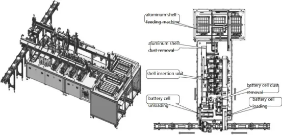
Case insertion pre-welding machine equipment is used for automatically inserting prismatic aluminum case batteries into the case. The main functio
ns of the equipment include: aluminum case loading, automatic battery loading and code scanning, aluminum case and battery core dust removal, battery core insertion, battery unloading, information binding and uploading (MES), etc.
Main technical parameters of the equipment.
Overall dimensions of the equipment: 2850mm×1900mm×2500mm.
Equipment yield rate: ≥99.8% (only refers to defects caused by equipment).
Equipment availability rate: ≥99% (only refers to failures caused by equipment).
Aluminum shell loading time interval: ≥25min; dust removal parameters are automatically recorded, and the battery core and aluminum shell will not be damaged during the dust removal process. No visible particles that can be wiped off.
To control the cell thickness, the clamping force needs to be increased: 10~50kgf (1kgf=9.81N) is adjustable, the debugging accuracy is ±5kgf, and the clamping pressure and vacuum value are digitally adjustable.
Thrust control accuracy during the casing process: ±5% of the setting value; the casing and battery cells are positioned twice before being inserted into the casing, and have the function of expanding the shell opening. The battery core adopts a fully surrounding guide mechanism to guide the battery core into the casing. The shell mouth of the aluminum shell cannot be touched at all.
Positioning deviation: 0.5mm.
Mechanism operation repeatability: deviation ≤±0.05mm.
2)Key Structures
From the equipment layout diagram of the shell pre-welding machine shown above, several key structures can be identified, including the aluminum shell feeding mechanism, aluminum shell and battery cell, top cover cleaning mechanism, battery cell insertion mechanism, and battery cell feeding mechanism. These structures play a critical role in the assembly of the final product. Let’s provide detailed explanations for a few selected mechanisms.
① Aluminum Shell Feeding Module (as shown in the diagram)
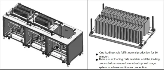
a. Function: realizes the feeding of aluminum shells, and has functions such as positioning and transfer of pallets.
b. Main components: stacking aluminum shell pallet automatic loading device, aluminum shell pallet, material transport trolley, etc.
c. Requirements: The aluminum shell feeding interval is ≥ 20 minutes; equipped with reliable guiding mechanism and positioning mechanism.
②Battery core and case dust removal mechanism (as shown in the figure).
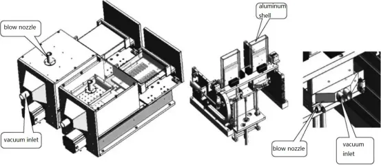
a.Function: The casing is cleaned vertically, and the blowing process covers all angles without obvious blind spots. The shell opening is treated specifically.
b. Main components: Dust removal mechanism, cylinder translation mechanism, etc.
3. Battery Cell Insertion Mechanism (as shown in the diagram).
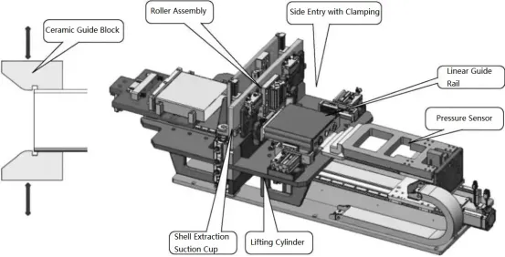
a.During shell insertion, the aluminum shell is secured, and the battery cell is clamped and pushed forward to protect the cell tabs.
b. The shell insertion process utilizes ceramic guide blocks with a large incline angle to prevent scraping of the aluminum shell, as well as damage or scratching of the separator.
c. Ceramic materials are used in the contact area with the aluminum shell.
d. After insertion, a 4mm gap is maintained for the subsequent pressing station, requiring the support bracket to enter the shell and ensure consistent depth of shell insertion.
e. Positioning accuracy: With a suction cup shell extraction structure, the shell is tightly positioned, achieving a positioning accuracy of ±0.1mm. The entire shell insertion process is monitored for pressure, and a standard weight is provided for calibration without disassembling the sensor.
f. The cleaning mechanism cleans the welding surface of the battery cell and shell cover by blowing from the upper sides and suction from the bottom.
g. The nozzle blowing angle and height can be freely adjusted, ensuring even airflow and forming an effective air curtain.
h. Cover pressing: Mainly used for Hi-pot testing of the battery cell after insertion. Prior to pressing, the dust around the cover plate is removed, and the cover plate is pressed into the shell.
i. Function: To insert the battery cell into the shell.
j. Main components: Shell insertion mechanism, lead screw assembly, shell extraction suction mechanism, etc.
4. Battery Cell Feeding Mechanism (as shown in the diagram).
a. Function: Used for conveying battery cells after insertion into the shell.
b. Main components: Battery cell clamping mechanism, lifting cylinder, conveyor mechanism, etc.
2.6 Pre-Welding Machine
1.Main Functions of the Equipment
The layout of the pre-welding machine is shown in the diagram.
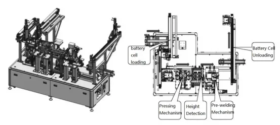
The layout of the pre-welding machine equipment is used for pre-welding the prismatic aluminum shell and cover plate. The main functions of the equipment include automatic battery feeding and scanning, pressing, height detection, laser welding, battery unloading, and information binding/uploading to MES (Manufacturing Execution System).
① Main technical parameters of the equipment:
Overall dimensions: 3000mm × 1800mm × 2500mm.
Yield of the equipment: ≥99.8% (referring to defects caused solely by equipment reasons).
Equipment utilization rate: ≥99% (referring to equipment failure caused solely by equipment reasons).
Hi-pot testing: Testing time ranging from 0.5s to 5s, adjustable within the range of 1s to 100s. The brand used is Hioki with an accuracy of ±5%. The testing voltage (DC) between positive and negative terminals is 100V, with a range (DC) of 0V to 500V and 50V increments.
Positioning deviation: 0.5mm.
Repeatability of mechanism operation: Deviation ≤±0.05mm.
2)Key Structures
From the layout diagram of the pre-welding machine equipment, it can be seen that the battery cell shaping and pre-pressing mechanism, step and short circuit testing module, pressing mechanism, pre-welding mechanism, as well as the cover sealing and pressing mechanism are critical and play a crucial role in the assembly of the semi-finished product. Let’s provide detailed explanations for some of these mechanisms.
① Battery Cell Shaping and Pre-Pressing Mechanism (2 sets, as shown in the figure)
a. Function: To shape and press the top cover of the battery cell after it is inserted into the casing.
b. Main components: Positioning components, lifting and pre-pressing assembly, etc.
c. Requirements: It should be capable of presetting the upper limit of pressure, provide an alarm and stop function when the limit is exceeded to prevent damage to the battery cell and casing. The pressure adjustment range should be 200 to 1000N. After pressing, the top cover should have no damage or debris, and there should be no burrs, burrs, or scratches around the casing opening. The pressing module should be designed with modularity for easy and convenient changeover.
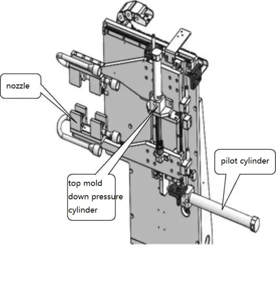
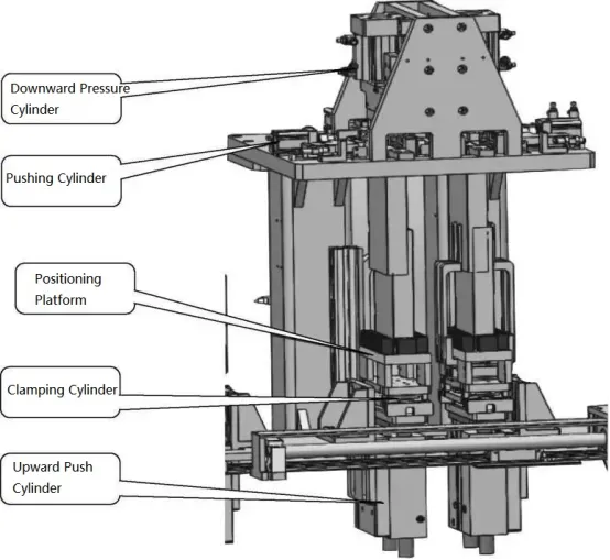
② Cover Sealing and Pressing Mechanism (as shown in the figure)
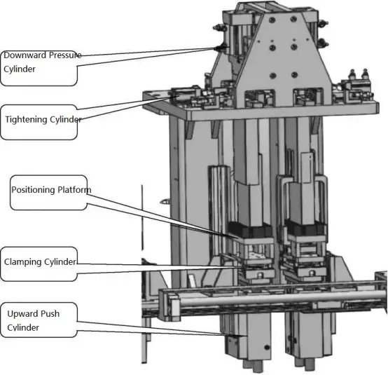
The specific operational sequence of the cover sealing and pressing mechanism is as follows:
a. Clamping Cylinder Action: Clamps the battery cell while the upward push cylinder lifts the cell to the assembly position.
b. Centering Cylinder Action: Clamps the battery cell, aligns it to the correct position, and releases the clamping cylinder.
c. Tightening Cylinder Action: Secures the shell and cover plate within the pressing mold, ensuring that the step is within 0.20mm. The mold has precise dimensions, high smoothness, allowing smooth movement of the shell and cover plate inside.
d. Suction Cup Assembly Action: Holds the shell and pulls it outward to prevent significant inward deformation.
e. Downward Pressure Cylinder Action: Guided by the pressing mold, presses the cover plate into the shell, while incorporating mechanical limiters to prevent excessive pressing.
f. Each cylinder has adjustable stroke length, and key parts are equipped with hydraulic cushions and fine-tuning limiters.
③ Pre-welding Mechanism (as shown in the figure)
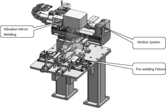
The “pre-welding mechanism” is primarily composed of a motion system and a pre-welding fixture.
a. Function: Laser focusing, defocus measurement, welding gas protection, and the motion system drags the laser head to scan the welding path.
b. Main components: The X and Y axes of the motion system adopt servo motors, laser welding machines, etc. The step detection sensor uses a 2D profilometer, with a step detection accuracy of ±0.02mm and steps less than 0.2mm.
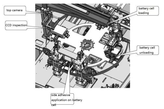
2.7 Top Cover Laser Welding Machine
1)Main functions of the equipment
The layout of the top cover laser welding machine is shown in the figure below. This equipment is mainly used for laser welding of the top cover of the battery cell after pre-welding and for Hi-pot testing. Its main functions include automatic barcode scanning for cell loading and unloading, automatic handling of protective cover plates, clamping and positioning, laser sealing welding, Hi-pot testing, NG buffering, and process transportation.
Overall dimensions of the equipment: 3000mm×4500mm×2200mm.
The first-time yield rate of equipment is ≥98.5%, the second-time excellent rate is ≥99.5% (excluding defective incoming materials), and the utilization rate is ≥98%.
Welding speed ≥150mm/s, CMK≥1.33.
Laser welding pressure strength>10kgf, CMK≥1.33.
Laser welding machine output power and fixture pressure control accuracy: set value ±5%, CMK≥1.33.
Welding quality (welding positioning accuracy ±0.1mm, weld width deviation ≤±0.1mm) consistency CMK≥1.33.
The environmental cleanliness of the protective cavity in contact with the product during the laser welding process is higher than the 100,000 level requirement.
The equipment functions can meet the needs of organization, communication and the docking of front and rear process equipment.
2)Key Structures
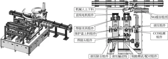
From the layout diagram of the top cover laser welding machine, we can identify several critical components such as the feeding mechanism, positioning assembly, protective cover feeding component, NG buffering, moving inspection component, CCD inspection component, NG handling component, unloading component, and welding head component. These components play a crucial role in the assembly of the semi-finished product. Let’s provide a detailed introduction to a few selected mechanisms.
① Top Cover Laser Welding Machine Feeding Mechanism (as shown in the figure).
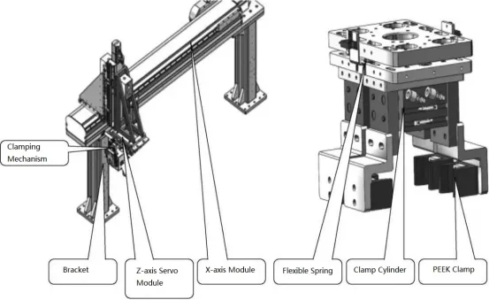
a. The loading mechanism includes a loading bracket, X-axis module, Z-axis module, clamping mechanism, etc. Use the loading clamp to grab the battery cores on the incoming material logistics line. Grab two batteries at a time and place them on the welding fixture. There are 4 sets of welding fixtures. Two batteries are placed at each time and the batteries are discharged twice.
b. The lifting mechanism of the manipulator is flexibly protected. When it encounters resistance before reaching the set position during the descending process, it will rise immediately and issue an audible and visual alarm.
c. The manipulator has a power and gas protection function. When the battery is clamped and the battery is cut off, the battery will not fall for at least 30 minutes.
d. Position and clamp the battery core so that its position is accurate and reliable during welding. The clamp block is made of high-temperature resistant materials. The welding positioning accuracy is ±0.1mm and the weld width deviation is ≤±0.1mm.
e. The height direction of the battery core is positioned based on the upper surface of the top cover. After the battery core is positioned and clamped, the height of the upper surface of the battery core top cover exceeds the upper surface of the clamping block by 1.5~2mm (determined by the customer). The upper surface level error is ≤0.1 mm, the repeatability error in height direction is ≤0.05mm.
f. During the positioning and clamping process of the battery core, the clamping block does not produce sliding friction with the battery core. A follower device is used to avoid pinching or scratching the battery core. After the battery core is positioned and clamped, the gap between the clamping block and the battery core is ≤0.05mm (standard piece).
g. The pressure of the cell positioning and clamping cylinder is adjustable, and the air pressure value fluctuates <0.05MPa.
② Upper positioning component (as shown in the picture).
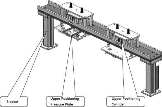
The specific action process is as follows:
a. The battery clamp moves to the upper positioning position through the A/B linear motor.
b. Control the solenoid valve of the long and short side positioning cylinder of the battery clamp to switch to the mid-discharge position.
c. The upper positioning moving cylinder drives the upper positioning pressure plate to press down to position the battery.
d. After the upper positioning is completed, the long and short side solenoid valves switch to normal pressure, and the upper positioning moving cylinder rises.
③ Protective cover loading assembly (as shown in the picture).
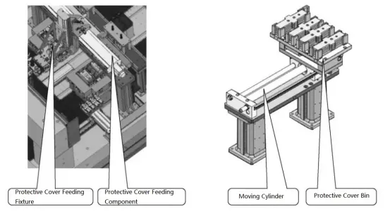
The specific action steps are as follows:
a. After the upper positioning is completed, the battery is moved to the upper protective cover position for protective cover feeding.
b. After the welding is completed, the system moves to the unloading position to remove the protective cover and unload the battery.
Note: The protective cover can be replaced without stopping the machine. The protective cover is used to protect the electrode column, preventing contamination of the electrode column, QR code, explosion-proof film, and injection hole from welding spatter.
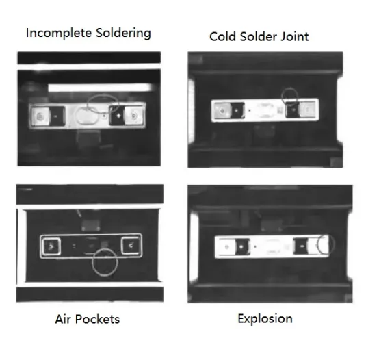
④ CCD Inspection Component (as shown in the figure).
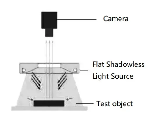
After welding, the battery cells are transported to the moving inspection component using the robotic arm module. The moving inspection component is equipped with two sets of clamps and has three stations: feeding position, inspection position, and unloading position. The CCD inspection component is equipped with a camera to detect defects such as pits, blowholes, soldering discontinuities, porosity, and incomplete soldering in the weld seam (as shown in the figure).
2.8 Positive Pressure Helium Leak Tester
1.Main Functions of the Equipment
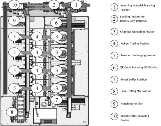
The layout diagram shown below depicts the positive pressure helium leak testing equipment. This equipment is primarily used for testing the sealing performance of prismatic aluminum shell battery cells after top cover laser welding. It employs a vacuum method to detect the sealing state of the top cover after welding. The working process is as follows: After the top cover is laser-welded, the tested battery cells are fed into the machine via a feeding conveyor and the top cover QR code is read. The sorting robotic arm then places the tested battery cells into the testing chamber. The chamber is evacuated until the set negative pressure value is reached, and then the external vacuum source is closed. The gas tightness tester is used to test the internal gas tightness of the battery cell. This device helps determine whether the tested workpieces are qualified.
The system is designed and manufactured in strict accordance with the requirements of the buyer, using a modular design, fully considering the leak detection requirements of the buyer, and using standardized modules and components as much as possible to ensure the reliability and maintainability of the system and meet the manufacturer’s requirements. Specify technical indicators.
The basic indicators of the equipment are as follows:
Equipment yield rate: ≥99.8% (except for defective incoming materials).
Equipment utilization rate: ≥99%; false detection rate: ≤0.3%.
Helium inspection standard: ≤9.9×10⁻⁷Pa·m3/s.
2) Key structure
This equipment consists of the following devices: workpiece inlet/outlet manipulator device, box slide, evacuation/helium filling device, vacuum box leak detection device, helium filling and removal device, and electrical control device. It can be seen from the layout diagram of the positive pressure helium inspection equipment in Figure 48 that the workpiece inlet/outlet manipulator device, evacuation/helium filling device, etc. are critical and play a vital role in the entire assembled semi-finished product. Several of these mechanisms are selected for details. introduction.
① Check the turntable. The main function of the detection turntable is to load and unload batteries and detect them at the same time, maximizing the effectiveness and efficiency of the air tightness detector. The module is mainly composed of a turntable, a cam divider and a detection fixture, as shown in the figure.
②Vacuum pumping mechanism (as shown below). The evacuation and helium filling parts are mainly composed of vacuum pumps, solenoid valves, pressure sensors and pipelines. The workpiece can be evacuated and filled with helium within a set time.
a. The helium filling pressure (absolute pressure) is 0.05~0.15MPa, which is adjustable within this range.
b. The system has helium pressure and concentration monitoring and helium automatic replenishment functions. When the system detects that the helium concentration or pressure is lower than the set value, it will automatically open the valve to replenish high-purity helium.
c. Recovery system: vacuum pump brand, Leybold; quantity, 1 vacuum pump, SV16B; 1 recovery pump (dry pump), Leybold.
d. Helium concentration meter: The concentration standard can be set.
e. The recovery rate of the recovery system is >80%.
f. The automatic helium cleaning function is intact and can quickly and effectively eliminate residual helium in the box and pipes. The leak detection accuracy and repeatability are reliable. Party B will provide standard leak holes.
03 Equipment selection and application cases
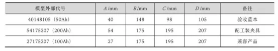
A customer has the following requirements for battery cell size.
①Customers provide technical information. The floor plan of the equipment model is shown in the figure, and its code name and dimensions are shown in the table.
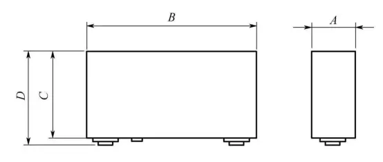
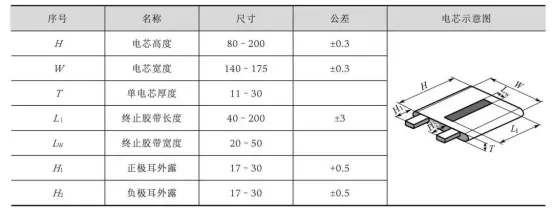
According to the customer’s needs, the cell specifications are clamped by adjusting the shared clamping hand. If necessary, the necessary pads can be replaced to achieve the production of cells of different specifications (such as jigs, fixtures, trays). Cell size specifications The variation range must not exceed the maximum size range of the device.
This automatic production line is used to realize the automatic assembly of prismatic aluminum shell lithium-ion power battery cells after winding. The production line mainly consists of the following parts: hot press machine, ultrasonic welding machine, adapter plate laser welding machine, and packaging machine. , shelling machine, pre-spot welding machine, top cover laser welding machine and logistics transmission lines between various equipment, etc.


